Hi-Fi is the abbreviation of High-Fidelity in English, which means high fidelity, which refers to the realistic restoration of sound source information, that is, the original taste. It requires the audio equipment to amplify and process the various indicators of the sound signal without distortion during the playback process to restore the original appearance of the sound source, emphasizing the original taste, mostly used to enjoy music. Hi-Fi amplifiers are signal amplifiers designed to reproduce the true nature of music with high fidelity.
Hi-Fi amplifier defects1. The AV amplifier is not strong enough when playing a large signal sound source
This can be seen from the product manual, the output power of the AV amplifier in the two-channel state is larger than the output power in the four-channel state. However, some manufacturers' instructions are the same. At this time, you can choose to listen to music with a large dynamic range, and you can obviously feel powerless. This is because the total power consumption of the AV power amplifier is large, and the power reserve of the power supply is not surplus, while the Hi-Fi power amplifier looks leisurely.
2. AV power amplifier routing affects sound quality
The AV amplifier is equipped with a variety of video and audio ports, which are connected to multiple sets of audio and video signal sources, resulting in many signal traces, which are very likely to cause mutual interference of signals. In particular, the presence of distributed capacitance has the greatest impact on treble and its harmonics, so that the original rich high-frequency components of high-quality signal sources are attenuated or interfered, so that listeners cannot appreciate the high-fidelity effect.
3. The fluorescent screen of the AV amplifier will also interfere with the sound quality
The AV amplifier focuses on convenient multi-function operation. The large fluorescent display on the panel makes the operation intuitive and vivid. However, the fluorescent screen is heated by low-voltage AC filament, and the character display is driven by the pulse signal, which will radiate a lot of electromagnetic interference to the surrounding. Affect the sound quality.
If you want to enjoy movies and movies, then choose an AV amplifier. If you have a soft spot for music, then choose a Hi-Fi amplifier.
Connection method of input signal line of Hi-Fi amplifierThe input part of Hi-Fi amplifier (take the amplifier as an example) refers to a section of signal transmission line from the input RCA socket to the volume potentiometer to the input stage voltage amplifier tube grid (see Figure 1). It is generally connected with coaxial signal lines (shielded lines), and is commonly used in fever-grade varieties, even silver wires. But usually just pay attention to the two segments of the volume potentiometer in and out, as shown in Figure 1 AB and CD two segments. The EF wire from the negative end of the RCA socket to the ground, and the GH wire from the ground end of the volume potentiometer to the ground wire are generally ordinary copper wires, even copper wires with a very small diameter, and some are due to the distance between F and H. Very long, it may be connected through a metal chassis. Although the amplifier can work normally in this connection method, even the sound effect is OK, but this connection is asymmetric and unbalanced to the signal input and output paths (positive half cycle and negative half cycle of the signal). It will have a certain influence on the speed, rhythm, details, positioning, etc. of the music. If the signal circuit is balanced and symmetrical, the playback effect will be greatly improved, especially the high frequency performance.
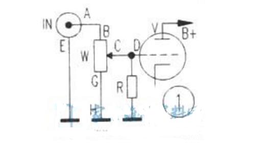
The reason is very simple. This is because the signal needs a smooth circuit when transmitting. The positive and negative half-circle circuits have different wires, different thicknesses, and different lengths. The resistance and distributed capacitance are also different. The loss is different. The performance of the sound effect It will be affected. Therefore, to make the amplifier have a more beautiful sound performance, it should be improved in the use of wires and connections.
The improvement method is very simple, as shown in Figure 2, the negative end of the RCA socket is connected to the ground end of the volume potentiometer (the middle is no longer passed through the ground wire), and the positive and negative terminals are connected to the volume potentiometer- -That is, A to B is equal to E to G, and each uses a coaxial signal wire of the same material, the same wire diameter, and the same length. The shielding layer is grounded at only one end. If the line segment CD is very short, the shielded line can be omitted. However, the material and diameter of the line should be the same as that used for line segment AB, and the line lengths of the two channels are equal, so the line is balanced and symmetric.
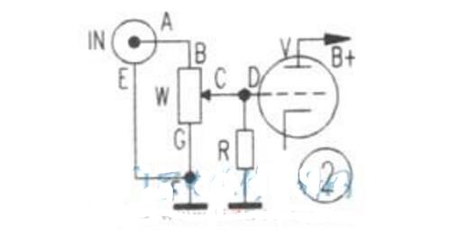
There are two-core and three-core varieties of bulk signal lines on the market. Each channel can use a section of two cores, one core is connected to A to B, one core is connected to E to G, and the shielding layer can be grounded. The three-core signal line can also be used. The extra one core is grounded together with the shielding layer. Never use one loop for one core, one loop for two cores, or one loop for each core, and leave the other core wire empty. Ground. It is better to use two-core or three-core small signal lines, because the two-core or three-core wires are gently twisted in the shielding layer, which can cancel the magnetic force lines, which is beneficial to the brightness of mid-range and treble. If you use a single-core coaxial signal cable, twist the two gently, but do not twist too tightly.
The symmetrical and balanced signal input circuit can make the music more perfect. If you are using a bile preamp or power amplifier, connect the grounding cable of the input RCA socket, volume potentiometer, etc. to the wire of the same material, length, and diameter as the signal terminal. Different, more beautiful sounds.
25W hybrid Hi-Fi amplifier circuit with tone control functionThe amplifier is made by the electronic tube as the pre-stage, and the audio special integrated circuit AD711 and LM1875 as the post-stage. The circuit has small distortion, low output impedance, and large dynamic range, which can ensure good sound quality.
1. The working principle of the circuitThis circuit only draws the left channel part, the right channel is omitted. The circuit selects a double triode 6N2 type electron tube to form a line input amplifier (half VE1L of 6N2 is used for the left channel, and the other half VE1R is used for the right channel). R2 is the DC bias resistance of the input stage. When the screen current Iao flows through R2, a DC voltage Eg of about 1.5V is generated, which is added to the gate of VE1L through the gate-drain resistance R1 to form the negative gate voltage of the line amplifier. At this time, VE1L works in Class A state and has good linearity. Another role of R2 is to generate proper AC feedback on the sound source signal, so that the distortion is further reduced and the stability is further improved; the third role of R2 is to form tone feedback. This input stage has outstanding advantages such as high input impedance of hundreds of thousands of ohms, large dynamic range, and good transient response, which is necessary for the Hi-Fi pre-stage.
An attenuated tone control network (TCN) is inserted between the front and rear stages. The audio signal output from the VE2La cathode K on the SRPP circuit is sent all the way through the volume potentiometer VR3 to pin 3 of the post-stage integrated circuit IC1; the other is fed to the cathode of the line amplifier VE1L via the TCN network. This combination can effectively suppress dry noise and distortion, while maintaining the adjustment characteristics of the attenuation type TCN.
The signal is amplified from VE1L and output from the anode. It is coupled to the power amplifier exciter VE2 composed of a high-frequency characteristic electron tube 6N3 through a capacitor C2. The two internal transistors are connected in parallel to adjust the push-pull circuit SRPP. The circuit is characterized by low distortion, low output impedance, and large dynamic range, and is fully adapted to various power amplifiers composed of IC, FET, TR, VAL, etc.
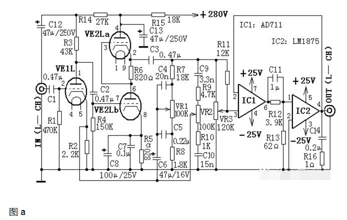
In Figure (a), capacitors C4 and C5, resistors R7 and R8, and potentiometer VR1 form a bass control network. When VR1 is turned up, the negative feedback of the low-frequency signal is increased by the network composed of C5 and C4, and the bass is relatively weakened. On the contrary, when VR1 is turned down, the bass will be relatively enhanced.
Capacitors C9, C10, resistors R9, R10 and potentiometer VR2 form a high-pitched control network. When VR2 is turned up, the amount of negative feedback of the treble signal increases, and the treble is relatively weakened; conversely, when VR2 is turned down, the treble will be relatively enhanced.
In the power amplifier circuit, we hope to get high fidelity and high power output. It is not difficult for general power amplifiers to provide large power to the load, but most of them have the disadvantages of large distortion and poor linearity. If a piece of precision op amp IC1 with good linearity and low distortion is inserted in the front end of the high-power IC, so that the power amplifier IC2 is in the feedback link of IC1, the effect of gaining strengths and avoiding weaknesses can be achieved. This connection is called "Turbocharged Combination" (TCC). Integrated circuits IC1 (AD711) and IC2 (LM1875) form the post-stage of the TCC power amplifier. In the TCC network, C11, R12, and R13 form an RC network, which provides moderate phase compensation for the audio signal and stabilizes the frequency response area of ​​IC1 and IC2.
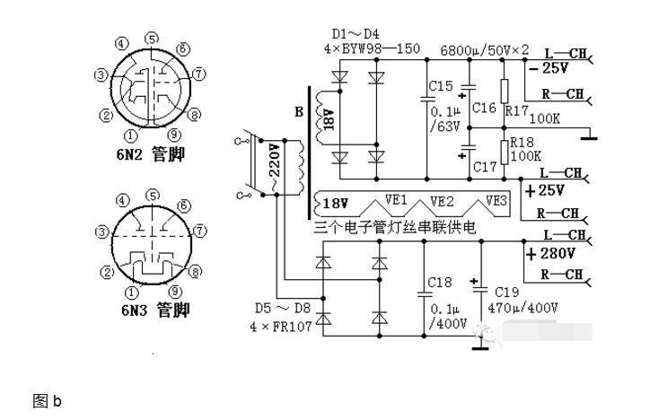
Figure (b) is the power supply circuit diagram of the whole machine. The front-stage high voltage of the electron tube is provided by 280V direct current generated by the rectification of the city power. The three filaments of the two electron tubes are connected in series, and the power is supplied by a set of AC 18V to make the circuit simple. Another set of AC 18V is bridge-rectified, C15, C16, C17, and filtered to produce ± 25V for IC1 and IC2.
2. Selection of componentsElectron tube VE1 selects 6N2, VE2 selects 6N3, integrated circuit IC1 selects AD711, IC2 selects LM1875, low voltage filter capacitors C16 and C17 select 70VW series, high voltage filter capacitor C19 selects CD17H series, C15 selects polyester capacitors, C18 selects polypropylene capacitors, C6, C8 selects tantalum electrolytic capacitors, C12 and C13 select CD03HV high-voltage electrolytic capacitors. All resistors use metal film series. Potentiometer use KK210 series. The component parameters are selected based on the circuit icon.
3. Production and debugging methodsSelect the components and install them correctly according to the requirements, you can succeed at one time without debugging. The electronic tube should be installed with an electronic tube holder, and the integrated circuit should be kept away from the electronic tube as much as possible to avoid overheating of the integrated circuit. After the circuit is installed, it should be installed in a chassis with heat dissipation holes, and the volume potentiometer and high and low tone potentiometers should be installed on the chassis panel for easy use and adjustment.
Four HI-FI power amplifier circuit diagrams 1, 100W * 2 HI-FI power amplifier circuitSTK2100-2 is a fever-level high-power power amplifier integrated circuit. Its output uses a power field effect tube with tube characteristics. The output power is 100W * 2, the frequency response is 10HZ ~ 20KHZ, and the minimum operating voltage of the circuit is plus or minus 12V, and the highest is Positive and negative 50V, distortion is 0.01%. Using it to make high-quality power amplifiers, the peripheral circuits are very simple, the distortion is small, and the parameters such as frequency band and output power have reached excellent indicators. The circuit is shown in Figure 5-84. VD3 is a speaker bridge pick-up circuit. When the power amplifier circuit is normal, RL only has an AC signal and no DC voltage, and the pick-up circuit does not work. VT1 ends, VT2 and VT3 turn on, K pulls in, and the amplifier output turns on the speaker. When the circuit fails, VT1 is turned on, VT2 and VT3 are turned off, K is released, and the speaker is effectively protected. ICI is a fever-level low noise, high conversion rate operational amplifier NE5535. The NE5535 output circuit is a PNP-NPN fully symmetrical complementary structure, with a certain static current bias, and the internal circuit is very simple. It has the advantages of open-loop frequency response, high unity-gain bandwidth, high conversion rate, low open-loop distortion, low noise and good transient characteristics. It is an ideal chip for using HiFi audio front-end circuit, and it is popular A base for op amps.
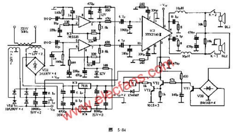
The power transformer of this circuit uses 250W ring type "fire bull", the power amplifier and the front power supply are separately supplied, and the high-quality high-capacity electrolytic capacitors are used, so the reserve power is large enough. All resistors in the circuit are high-quality metal film resistors. Capacitors use tantalum and CBB capacitors. Therefore, the sound of the whole machine is small, the midrange is bright and clear, the bass is strong and thick, and it has the flavor of "guts".
2. Inexpensive and sound bedside HI-FI amplifier circuitThe self-made power amplifier is TL082 and TDA1521, and the circuit is shown in Figure 5-74 and Figure 5-75. The power supply voltage of the machine should not be higher than the double 14V, but the power should not be lower than 20W. The double 12VE type transformer is used, and the resistance is all 1 / 4W5 ring gold film. Domestic monolith and Shenlun are used for capacitor. The input of TDA1521 uses SANYO's 47pF / 6. 3V organic solid capacitor, 560pF / 35V electrolysis is a common product of ELNA. There are several imported capacitors here, which are related to sound quality, not tolerant, but the price is higher. Amplifier cooling uses a 486 cooling fan, basically no interference noise.
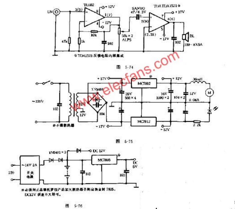
The sound book is made by fixing the two South Whale YD-110-8SXA speakers in the plastic shell of the car's top speaker. Its frequency is 80 ~ 10000Hz. The low frequency is not deep but the response is fast and accurate. In fact, the fundamental pitch of musical instruments is not much higher than 8000Hz. Trial release of Tchaikovsky's No.-~ Steel Spear Concerto "81812", I feel that the piano sound is more accurate in most cases, brass instruments can make you feel brilliant, the sound of cannon dives can not be said, the sound pressure The level is not big, but very clear. The connection adopts 30 strands of "gold and silver" wire of 1 yuan / meter. This speaker is the largest magnet in 4 inches, similar to some 6.5 inches magnets, and shielded, can be used as the center or main sound into the midrange.
The power supply adopts "UPS", a 14V / 2A switching power supply generates all voltages, and is powered by a battery when the power is turned off (light off), the circuit is shown in Figure 5-76. The battery capacity should not be less than 4Ah. It can also drive a power at night The fan blows through the air and lights a small light bulb to read a book.
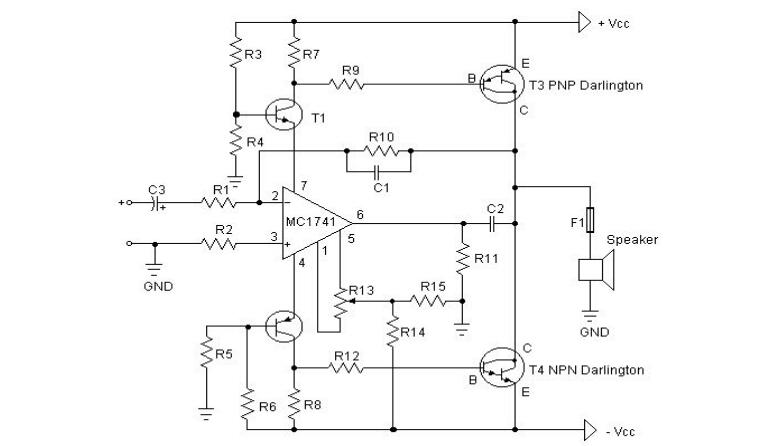
3. Hi-Fi power amplifier circuit with BOMExplanatory notes:-The first thing you have to do is to test the amplification factor hfe or β of the final power tube. If their difference is greater than 30%, the amplifier will not provide you with a clear sound. I use MJ3001 and MJ2501 transistors, and their difference is 5%.
Before turning on the power, you must short-circuit the input terminal, connect an ammeter to the output terminal of the amplifier, and then turn on the power, adjust R13 to make the ammeter current to microampere level, if you are lucky enough, you may be able to reach 0, the ammeter current is at 10 micrometers Ampere is very easy to do.
Power amplifier circuit diagram:
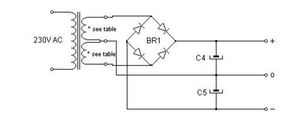
Power circuit:
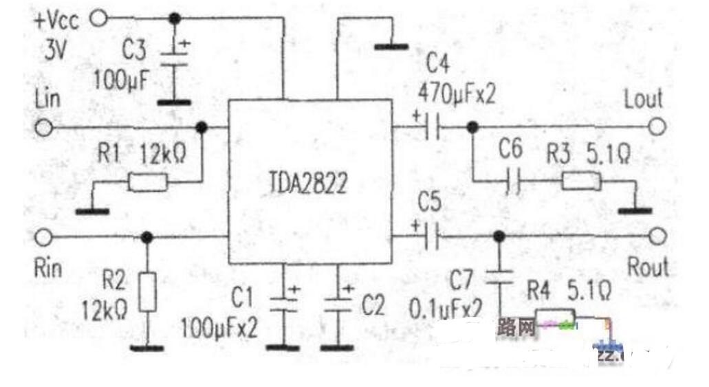
The amplifier uses the commonly used TDA2822 small power amplifier block (which is very easy to buy on the market). The TDA2822 is an 8-pin dual in-line plastic packaged integrated block, which has a small size and a large output power. No radiator is required. The whole circuit has few components, the power supply voltage is DC 2V ~ 15V, the quiescent current and distortion are very small, and it can work in the stereo state or the BTL state.
The circuit principle is shown in the attached drawings. All the components used in the figure are common components, the resistance is 1 / 4W, and the capacitor withstand voltage is 25V. This circuit is a two-channel circuit, Cl and C2 are coupling capacitors, play a DC blocking role, C3 is a power supply filter capacitor, C4, C5 are output coupling capacitors, Rl, R2 are bias resistors, R3, R4, C6, C7 function It is to prevent self-excitation. This circuit uses 3V DC power supply. If conditions permit, a higher voltage can be used to increase the output power, but the maximum voltage should not be higher than 15V. The speaker adopts 8Ω1W or 4Ω2W, the larger the caliber, the better.
Waveguide Load,Waveguide Dummy Load,Waveguide Termination Load,High Power Waveguide Load
Chengdu Zysen Technology Co., Ltd. , https://www.zysenmw.com
