
0 Preface
Temperature is one of the most common and important physical process parameters in industrial production. With the development of society, the requirements for temperature measurement in the industry are getting higher and higher, and the range of measurement data is getting larger and larger. When the temperature acquisition system is designed, the design of the sensor module will directly affect the measurement effect of the data. As the measurement requirements increase, the complexity of the sensor module circuit will become higher and higher, which will undoubtedly bring difficulties in wiring and decrease in efficiency. At the same time, there are hidden dangers such as easy short circuit and easy aging, which brings difficulties to the comprehensive debugging and maintenance of the system. Compared with traditional wired communication technologies, wireless transmission technology has the advantages of high measurement accuracy, low environmental impact, and low cost. This paper combines sensor technology with wireless communication technology to achieve wireless temperature acquisition.
1 Principles of system design
The wireless temperature acquisition system is a wireless temperature detection device based on radio frequency technology. In the system, the analog signal outputted by the temperature sensor is sent to the signal amplifying circuit, the low-pass filter and the A/D converter (ie, the signal conditioning circuit), and then the A/D converter is output under the control of the single chip microcomputer. The digital signal is transmitted to the wireless transceiver chip, and is transmitted to the upper computer through the internal antenna of the chip through the modulation processing of the chip. In the upper computer module, the transmitted data is received and demodulated by the wireless transceiver chip controlled by the single chip, and finally It is sent to the PC through the interface chip for display and processing.
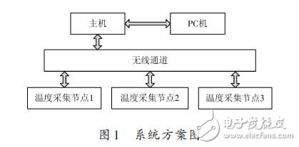
The system includes three communication nodes: wireless acquisition, host control and PC: wireless acquisition node realizes temperature acquisition and temperature data transmission and reception; host control node realizes simple communication control and wireless data transmission and reception, and can be transmitted to the host computer through the serial port; PC The node provides computer communication mode for data acquisition, and provides a PC software design platform for realizing more powerful functions. The system design scheme is shown in Figure 1.
2 hardware design
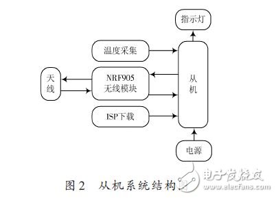
According to the set system scheme, the specific design of the hardware circuit is carried out. Since the hardware design principles of the modules of the master and the slave are basically the same, the temperature acquisition and the NRF905 wireless communication block are all in the slave part. Here, the hardware of the slave is analyzed. Design, system structure diagram shown in Figure 2.
2.1 Temperature collection
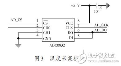
The main function of the temperature acquisition module is to digitize the analog quantity. Here, the ADC0832 chip of successive approximation analog-to-digital converter is used. The chip has 8-bit resolution and the conversion range is 0~5 V. Since the input and output of data are not at the same time This is done, so DI and D0 can be connected to the same pin. The ADC0832 communicates with the microcontroller using the SPI serial interface with a supply voltage of +5 V and a decoupling capacitor C of 0.1 μF. The hardware circuit is shown in Figure 3.
2.2 NRF905 wireless communication
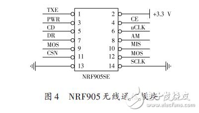
The wireless communication module uses a single 433/868/915 MHz wireless transceiver NRF905 chip. The interface between the chip and the single chip microcomputer is SPI port, and the modulation adopts GFSK Gaussian frequency shift keying mode, which has strong anti-interference ability. The band adopts ISM free band, the power supply voltage is 1.9~3.6 V, and the power is 3.3 V. The device uses AMS1117-3.3, and the transmitting power is up to 10 dBm. The hardware circuit is shown in Figure 4.
The Optical Fiber Jumper wire is used to make the jumper wire from the equipment to the fiber wiring link. There is a thicker layer of protection, generally used between the optical terminal and the terminal box, and used in some fields such as optical fiber communication system, optical fiber access network, optical fiber data transmission and LAN.
LC To ST Fiber Optic Patch Cord
Optical Fiber Jumper,LC To ST Fiber Cable,ST LC Fiber Patch Cable,Indoor Fiber Optic Cable
Chengdu Xinruixin Optical Communication Technology Co.,Ltd , https://www.xrxoptic.com