
Generally speaking, for the output voltage of the inverter, we are concerned about the effective value of the fundamental wave. The 380V and 690V inverters we often say, as well as the voltage value displayed on the inverter panel, refer to the effective value of the fundamental wave. .
For multimeters, most of them can only measure the effective value of power frequency sine waves, and some high-end multimeters can measure the true effective value of non-power frequency and non-sinusoidal signals. The true effective value is different from the fundamental effective value. Take a 380 volt inverter as an example. When the rated output is measured with a true RMS multimeter, the voltage can reach 450 volts or even more than 500 volts (related to the bandwidth of the multimeter. Within a certain range, the wider the bandwidth, the greater the measured value, and the closer it is True true effective value).
Take a 380 volt inverter as an example. When the rated output is measured with a true RMS multimeter, the voltage can reach 450 volts or even more than 500 volts (related to the bandwidth of the multimeter. Within a certain range, the wider the bandwidth, the greater the measured value, and the closer it is True true effective value).
Therefore, the multimeter cannot be used to measure the output voltage of the inverter. Unless the output is a frequency converter with a sine wave filter installed.
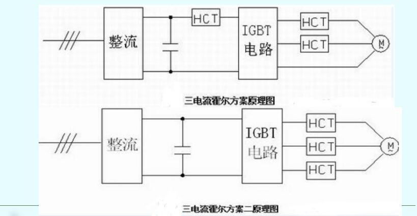
Current Hall scheme:
The Hall current sensor is a new generation of current sensor using the principle of Hall effect, which can measure the current of DC, AC, pulsating and various irregular waveforms under the condition of electrical isolation. Since the response time of the closed-loop Hall current sensor is less than that, when a short circuit occurs, the Hall output current signal is converted into a voltage signal by the sampling resistor and sent to the DSP in time. The PWM drive signal output is closed within the IGBT 10us short circuit safety time to make the IGBT reliable protection of. Of course, like the voltage hall, the power supply voltage required for the normal operation of the current hall must be provided, and the error of the power supply voltage should not exceed ±5%. When selecting the current Hall element at the same time, the linear range must meet the range of the maximum operating current of the IGBT.
In the three-current Hall scheme, the DC side Hall is used to detect the bridge arm through fault, which has higher requirements for response indicators. The output side two-phase current detection is used to complete dead zone compensation, no trip current closed loop, overload, overcurrent current Detection. In the three-Hall scheme 2 in the figure, the DC-side Hall is removed, and the through protection is ensured by intelligently driving the optocoupler. In addition to the two-Hall function in the figure, the output-side three-Hall function can also be used for output phase loss detection.
Linear optocoupler solution:
The output current of the inverter is sampled by a low resistance, low inductance, and high-precision sampling resistor, and the obtained voltage signal is isolated and amplified by a linear optocoupler, and then sent to the DSP. The inverter is protected by the internal processing of the DSP. The specific circuit Can refer to the circuit of linear optocoupler in voltage measurement, but the input signal terminal is slightly different. This usage is commonly used in small power inverters. The selection of the sampling resistor value should take into account the two factors of minimum power consumption and maximum accuracy.
Performance requirements for voltage and current sensors in inverter design1. Electromagnetic compatibility requirements With the widespread use of frequency converters and other power electronic devices, the electromagnetic interference of the system is becoming more and more serious. The corresponding anti-interference design technology (ie electromagnetic compatibility EMC) has become more and more important, which requires voltage and current The sensor's own anti-interference ability should be strong.
2. Power supply requirements
±15 volts ± 5%, in actual applications, the accuracy and cleanliness of the power supply are required to be high, otherwise it will easily cause the measurement output to be inaccurate, and even the sensor may be damaged by heat.
3. Temperature characteristic requirements
The working environment temperature requires -10~+70℃. As the temperature increases, the output of the sensor is required to be affected as little as possible by the temperature.
4. Linearity requirements
The linearity of different series of voltage and current sensors is different. The linearity ≤±0.1%FS is used in the design of high-performance inverter, and the linear range should be greater than the maximum value of the measured current.
5. Volume requirements
The smaller the volume, the better, and the performance is stable.
6. Response time requirements
The response time of different series of voltage and current sensors is different. Generally, a sensor with a smaller response time is selected, such as Tr ≤1μS.
Ningbo Autrends International Trade Co.,Ltd. , https://www.vapee-cigarettes.com