Many modern FPGA designs use embedded processors for control. A typical solution requires the use of embedded soft processors such as NIOS. Another solution uses SoC devices that contain a built-in hard processor. Figure 1 shows a typical Altera FPGA system, which includes a processor and a series of peripherals connected via an Avalon memory-mapped (MM) bus. These processors greatly simplify the final application, but require developers to have a solid programming background and knowledge of sophisticated tool chains. This will hinder the advancement of debugging, especially if hardware engineers need a simple way to read and write peripherals without disturbing software engineers.
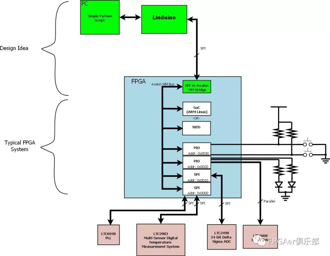
Figure 1: A typical Altera FPGA system connected via the Avalon memory mapped (MM) bus
This design idea uses Altera's SPI from the end to the Avalon MM bridge to provide a simple way to jump on the Avalon bus. There are two advantages to using this approach: it does not harm the original system design, and the bridge can coexist with the embedded processor. For the system shown in Figure 1, the SPI-Avalon MM bridge will allow designers to directly control the frequency of the LTC6948 fractional N PLL, set the LTC1668 DAC voltage, read a voltage from the LTC2498, or read the temperature from the LTC2983, just like The processor is the same.

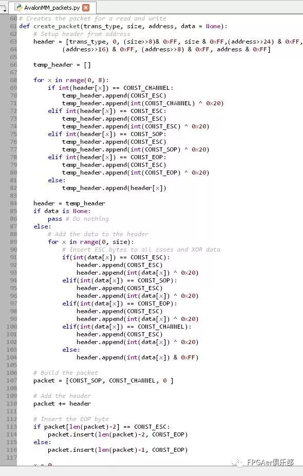
Figure 2: Highlighter + sample code + reverse engineering = Python script
After reverse engineering the Altera example design (left side of Figure 2), a Python library is developed to generate the data packets that the bridge will accept. These data packets are then converted into Linduino commands. In this way, a simple Python script enables the hardware engineer to fully control the project without completely changing the interface protocol. A Python script example for controlling the frequency of the digital graphics generator used in the LTC1668 DAC is provided in the LinearLabTools Python folder, which can be obtained by logging in. Figure 3 shows the demo setup.
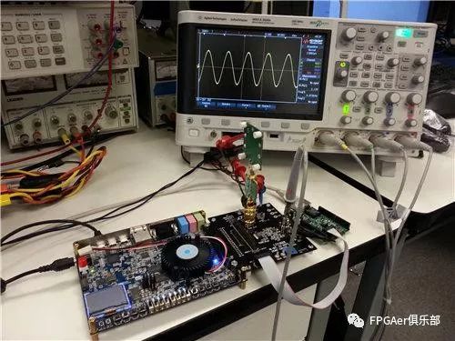
Figure 3: DC2459 at work
Figure 4 shows the block diagram of the FPGA system. Please note that the digitally controlled oscillator (DCO) can be controlled by the shift register or the PIO core. The built-in shift register is used for debugging because it provides direct control of the NCO. Setting the logic level of the GPIO line to "high" will enable the SPI-Avalon MM bridge, which then controls a 32-bit PIO port through the Avalon MM bus. Then, the PIO output controls the NCO frequency.
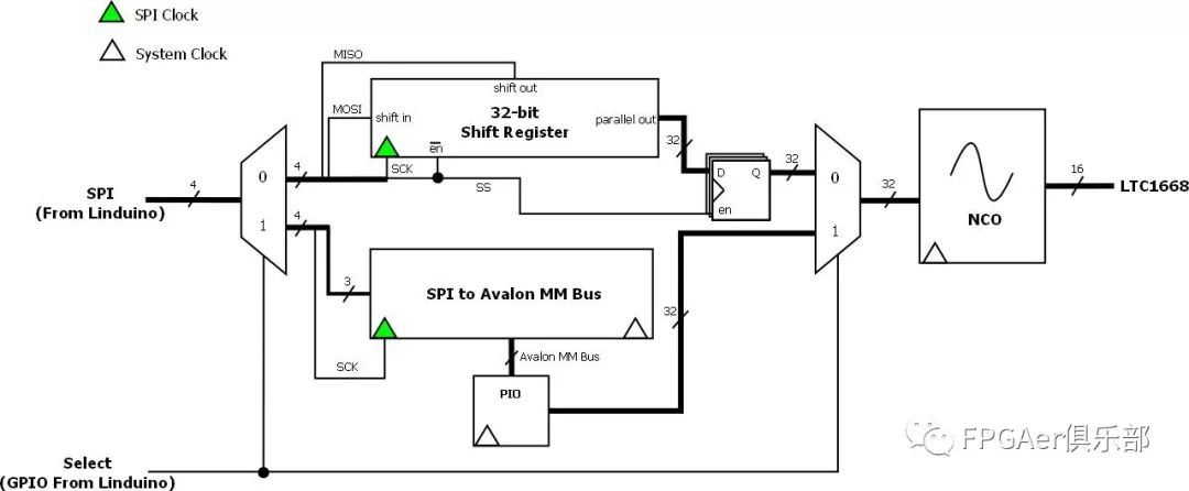
Figure 4: DC2459A FPGA system block diagram
When the most basic system is running, additional Avalon peripheral IP cores can be connected to the Avalon MM bus. To design the system, Altera provides a system integration tool called Qsys. This tool provides a GUI to connect IP to each other. Qsys was subsequently used to translate the GUI system into hardware description language (HDL) Verilog. Figure 5 shows the GUI. Finally, the system will be added to the top level for implementation. The IP address is fully configurable. For the example given, PIO is set to a base address unit of 0x0.
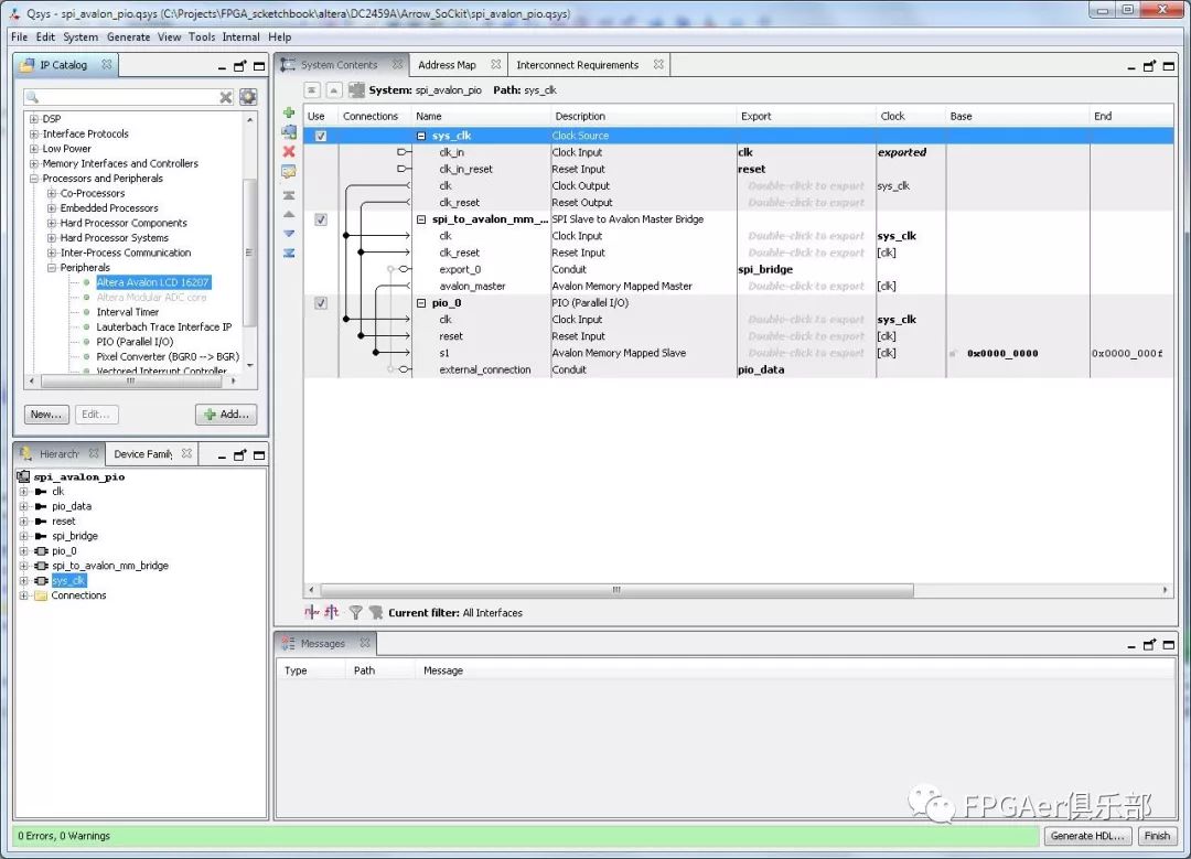
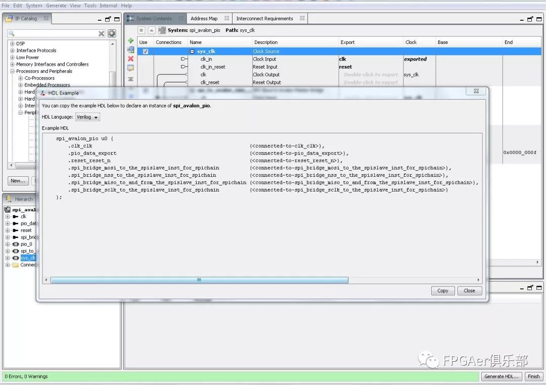
Figure 5: Qsys GUI
Once the design is implemented in FPGA, the Python library provided in LinearLabTools contains two functions to interface with the design:
transaction_write(dc2026, base, write_size, data)
transaction_read(dc2026, base, read_size)
The first parameter of these functions is the Linduino serial port instance. The second parameter is the address of the peripheral on the Avalon bus. These functions accept and return byte lists respectively. These two functions are written to provide flexibility when reading and writing IP. To set the NCO for the provided instance, all you need is the transaction_write function.
Equation 1 is used to determine the frequency control word.
Formula 1: Frequency control word = (desired frequency/system clock frequency) x 232
If you want to set the NCO to 1kHz and a 50Msps sampling rate, the frequency control word value = 85899. The value expressed in hexadecimal is 0x00014F8B, which is passed as a 4-byte list. So, the Python code for setting the DAC to 1kHz is:
transaction_write(linduino_serial_instance, 0, 0, [0x0,0x01,0x4F, 0x8B])
Note: According to logic design, the base address of PIO is zero.
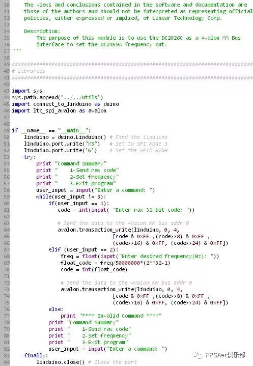

Figure 6: Python Avalon bus example
A simple Python script as shown in Figure 6 is provided to demonstrate the interface between FPGA design and Python script. It contains a simple text interface to configure NCO. An important note is that the Avalon SPI bridge uses SPI Mode 3. It is painful to determine the correct mode through trial and error; and to verify it by analyzing the SPI interface of the NIOS processor in the Altera example.
In summary, this example project demonstrates the ability to control the system without "touching" the embedded processor. This allows hardware engineers to make progress on projects without bothering software engineers. The benefits of this method can be quietly added to the FPGA without affecting the original design. Hardware engineers can concentrate on the hardware.
1000W Solar Generator
Super Green Energy Portable Solar Generator Battery Energy Storage System USB Power Station for Outdoor Picnic
1000 Solar Generator,All In One Solar Generator,Outside Home Off grid Portable Solar Generator
suzhou whaylan new energy technology co., ltd , https://www.whaylan.com
