
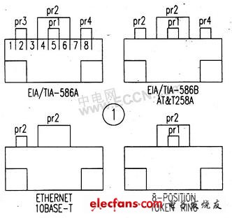
In the era of the global village where the Internet is everywhere, the Internet has changed people's traditional way of life. Now that computer technology is advancing by leaps and bounds, broadband has entered thousands of households, and network access can take many forms, such as unit LAN, ADSL, ISDN, MODEM, power carrier broadband and so on. The most commonly used connection medium is five types of twisted pair, which has been widely adopted by network engineering. When we build a network, we often use RJ45 connectors, and use crimping pliers as interfaces for various specifications, as shown in Figure 1. The quality of the interface is very important, it affects the success of the network connection. After the network cable is ready, use a network cable tester to test. Here is a brief introduction to the working principle of a simple network cable tester, you can DIY.
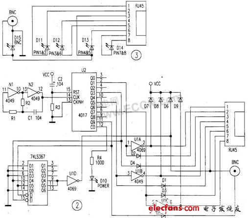
The network cable tester is divided into two units: one part is the sending unit, which is powered by a 9V laminated battery, and has a power switch and a green power indicator. The other part is the receiving unit, there are 5 light-emitting diodes to indicate the network cable connection status. The circuit is shown in Figure 3.
Sending unit
The circuit principle is shown in Figure 2, which uses three integrated circuits and a small number of peripheral components. CD4069 is a six-inverter, composed of multivibrator and LED drive circuit, CD4017 is a decimal counter pulse distributor. Assigned to the network cable proper test pulses, 74LS367 is a six-bus driver that assists in generating network cable test pulses.
2. Working principle
In Figure 2, the two inverters N1, N2 and R1, C1, R2 inside the CD4069 form a positive feedback network, forming a multivibrator, generating rectangular pulses. The pulse signal is added to the ⒠pin (CLK terminal) of the decimal counter / pulse distributor CD4017, and the ⒂ pin (RST terminal) of the CD4017 is reset when power is turned on, and the ⒀ pin (CKINF1 terminal) is grounded to count the input pulse. Pulse signals are output from Q1, Q3, Q5, Q7, Q9, and CO, and the pulse output by QI is applied to the positive electrode of D2 to make D2 conductive. The pulse signal of Q1 is added to the ①pin of CD4069 (U1A) at the same time, so that its output pin ② becomes low level, the current flows through D2, the ①pin of the sending unit interface RJ45, the tested network cable, and the ①of the receiving unit interface RJ45 Pin, D11, ② of the receiving unit RJ45 returns to the sending unit. If D1 1 is lit, it indicates that the network cable of ①pin and ② pin is connected. The pulse output from Q3 is added to the positive pole of D4, and at the same time to the ⒂ foot (E2 end) and D4 end of the six-bus driver 74LS367. The signal outputs a high level from Q4 via 74L-S367, and the U1D inversion of 4069 causes the RJ45 of the sending unit The ⑥ pin becomes low level, and the current is output to the receiving unit through the ③ pin of the sending unit and the tested network cable. After D13, the ⑥ pin of the receiving unit tests the ③ and ⑥ pins of the network cable. In the same way, the pulse output from the Q5 pin is added to the positive pole of D1 and the ③ pin of CD4069 (U1B), and the output low level of the ④ pin of CD4069 (U1B) is added to the ④ pin of RJ45 to complete the test of the ④ and ⑤ pin network cables. . The pulse output from Q7 is applied to the positive pole of D3 and the ⑤ foot of CD4069 (U1C) to complete the test of the ⑦ and ⑧ foot network cables.
If the network cable is connected incorrectly, the flowing circuit changes, and the light-emitting diode lighting state changes, so you can determine whether the connection mode is correct. If the test is a BNC interface, the pulse output from Q9 is applied to the positive terminal of D5 and the D5 and E1 terminals of 74LS367, Q5 outputs a high level, and is added to the other end of BNC via 4069 (U1D), and the BNC interface is tested. The CO terminal of 4017 will also output pulses to DIO via R4, and the power indicator will flash.
3. Test results
D11 represents the state of the ①and ② feet of RJ45, D12 represents the state of the ④ and ⑤ feet of RJ45, D13 represents the state of the ⑨ and ⑥ feet of RJ45, D14 represents the state of the ⑦ and ⑧ feet of RJ45, and D15 represents the state of BNC. When the network cable is normal, the LED is green; when the circuit is open, the LED is off, and the connection status of the network cable can be determined according to the LED lighting sequence
Constant Voltage Transformer,Laminated Transformer,Encapsulated Transformer,12V Ac Transformer
IHUA INDUSTRIES CO.,LTD. , https://www.ihua-transformer.com