
USB 3.0 port ESD protection scheme
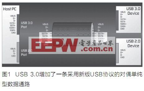
The ubiquitous Universal Serial Bus (USB) interface is about to welcome another generation change in order to keep up with the growing demand for connection bandwidth. USB3.0 or so-called "SuperSpeed ​​USB" is expected to take a big step forward in terms of transfer speed, power management and flexibility. The development direction of USB 3.0 includes providing higher transfer rates, increasing maximum bus power and device current, providing new power management functions, and new cables and connectors that are backward compatible with USB 2.0. The most significant change is the addition of a physical bus parallel to the existing USB 2.0 bus, see Figure 1.
The improvement of USB 3.0 current transmission capability has strengthened the demand for new circuit protection solutions. A cooperative circuit protection method will help prevent damage due to overcurrent, overvoltage, and ESD (electrostatic discharge) transients in USB 3.0 applications.
Overcurrent protection
USB 3.0 is powered by two types of devices: standard main control equipment (type A connector) and new power supply equipment (Powered-B connector). The new SuperSpeed ​​specification increases the amount of current flowing to the USB device-from the maximum rated current of 0.5 A to 0.9 A. The Powered-B connector can charge the device by delivering up to 1.0 A from two additional connectors.
Since overcurrent conditions affect the power bus, all power sources (such as hosts and hubs) require overcurrent protection.
The main advantages of the new Powered-B connector are improved portability, convenience, and power efficiency. By adding two additional contacts, the new connector allows one electronic device to provide up to 1000 mA to another electronic device. For example, a printer can power a wireless adapter, so there is no need to connect to a wired network.
Similar to USB 2.0, all types of USB 3.0 connectors have power supply capabilities. The single device load of USB3.0 is increased from 100 mA of USB 2 to 150 mA. An electronic device can drag up to 6 devices (standard connector and mini connector up to 900mA per port). The standard USB 2.0 connector application remains unchanged in USB 3.0. However, although the USB 2.0 hub can be powered by the bus, USB 3.0 will not provide this option, but can only be powered by its own power supply.
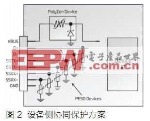
Since a jack port is required to power all connectors in a USB 3.0 hub application, circuit protection devices are required on the jack to prevent damage due to overvoltage events, which may include unregulated power supplies, reverse voltages, or voltages Transient. Figure 2 shows the method of installing Tyco Electronics' PolyZen device on VBUS and the installation of six small-capacitance PESD devices on the device port to help achieve a coordinated overcurrent / overvoltage protection scheme.
In addition, for systems that support USB charging, overcurrent protection devices with high current capability are also required. PolySwitch Polymerized Positive Temperature Coefficient (PPTC) devices can provide a cost-effective USB overcurrent protection solution. As shown in Figure 3, installing a PolySwitch device on the VBUS port helps prevent overcurrent damage caused by a sudden short circuit on the downstream side of the device and reduces the power loss required in various USB applications.

Overvoltage protection
USB overvoltage protection devices designed for traditional 0.5A ports are not suitable for the new USB specification of 0.9A per port. If a 0.9A host is disconnected, a high induced voltage spike will occur, which will negatively affect the devices that are still on the bus. A well-designed bus will absorb this spike and prevent the device from contacting it. Various interfaces and charging systems will expose portable electronic devices to the risk of damage due to the use of incorrect chargers, poorly regulated third-party chargers, or hot swap events. Although a typical USB power supply has a regulated line of 5V ± 5%, under special circumstances, the voltage on these lines may also greatly exceed 5.25V. The interface and charging system also generate negative voltages, which can damage peripheral devices that have not taken protective measures.
Tyco Electronics' internal testing shows that the transient caused by hot swapping, although short in time, may have a voltage amplitude exceeding 16 ~ 24V. Internal testing also found that the open circuit voltage of the third-party charger exceeded the USB specification requirements of 5V ± 5%. Installing overvoltage protection devices (such as PolyZen polymer protection zener diode devices) on all USB powered devices, especially VBUS ports, can effectively prevent damage due to voltage transients. For USB 3.0 devices, PolyZen devices can be placed on the USB input port, Power-B plug, and female jack power port as appropriate.
ESD protection
Overvoltage transients are often caused by ESD, and may appear on both the power bus and the data bus. Although modern integrated circuits can withstand voltages up to 2000 V, the human body can easily collect static electricity up to 25000V. In I / O port protection applications, very low capacitance ESD devices with fast clamping and recovery response are required on the data line.
The existing USB 2.0 protocol supports a data transfer rate of up to 480Mbps, plug and play, hot plug installation and operation. In comparison, the USB 3.0 specification supports data transfer rates up to 5Gbps and is backward compatible with the low-speed USB 2.0 specification.
USB 3.0 adds four new pins to the connection to support the new SuperSpeed ​​interface: USB3_TX (differential pair) and USB3_RX (differential pair), as shown in Figure 4.

USB 3.0's SuperSpeed ​​interface requires lower ESD protection than USB 2.0 capacitors. Adding very low capacitance PESD devices can reduce insertion loss and meet the USB 3.0 eye diagram requirements. The typical capacitance of PESD devices is 0.2pF, the insertion loss is stable over 6 GHz, and it can cope with various ESD transients.
Compared with most traditional MLV (multilayer varistor) or TVS (transient voltage suppression) diode technology, PESD devices have lower capacitance, and their low trigger voltage and low clamping voltage also help protect sensitive electronic components. The device is suitable for USB2.0 high-speed D + and D- signal lines and USB 3.0 SuperSpeed ​​signal lines. The addition of PESD devices in the circuit protection design can achieve the protection level that meets the requirements of the IEC61000-4-2 standard, which specifies the contact mode to be 8kV (typical) / 15kV (maximum) and the air discharge mode to be 15kV (typical) / 25kV (maximum).
Cooperative circuit protection

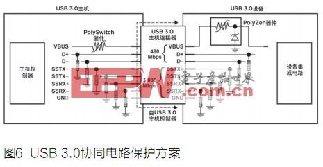
The cooperative circuit protection design can be used to improve the protection of high current, high voltage and ESD transients in USB applications. Figures 5 and 6 show the additional circuit devices required by the USB 3.0 design and compare it with the USB 2.0 design.
Device recommendation
PolySwitch overcurrent protection devices can help designers meet the high current requirements of the USB 3.0 specification and provide simple, space-saving solutions. PESD devices have the low capacitance (typically 0.2pF) required for high-speed data transmission applications and the most common form factor for the electronics industry. PolyZen devices can provide designers with the ease of use of traditional clamping diodes without requiring a lot of heat dissipation. This single device helps protect against the use of incorrect power supplies and also prevents damage due to overcurrent events.
Tyco Electronics recommends the following devices for ESD protection:
USB 2.0 high-speed D + / D- cable and USB 3.0 SuperSpeed ​​cable:
â— PESD0402-140 (EIA 0402 specification)
â— PESD0603-240 (EIA 0603 specification)
5VDC line:
â— PESD: PESD0402-140 (EIA 0402 specification), or
â— MLV: MLV0402-120-E120, MLV0402-180-E030 or
MLV0603-130M-C201
Tyco Electronics recommends that the devices used in USB overcurrent protection are shown in Table 1.
Tyco Electronics recommends installing overvoltage protection devices on all USB powered devices, especially on the VBUS port, as shown in Table 2.
European Series Extension Sockets
Wall Electrical Outlet,Multi Plug Wall Socket,England Outlet Adapter,Wall Mounted Multi Socket
Heikki Technology Co., Ltd. , https://www.heikkipower.com