
First, the difficulty in memory testing
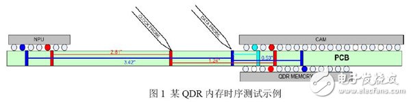
Memory is widely used in various electronic products. Memory testing is also a hot and difficult point in product testing. The most critical test item in memory testing is the timing relationship between DQ/DQS/CLK. The JEDEC specification states that when measuring the timing between these signals, the test points need to be selected near the very end of the memory. Most of the current memory chips are BGA packages, and some are even positive and negative. Sometimes it is difficult to find test points at the end of the memory chip for testing. If the test is performed in the middle of the link, the signal is on the one hand. There will be reflections back to the ditch, etc., which affects the timing test. On the other hand, the position of the test points of different signals is different, and the measured timing is not a real time series result. As shown in Figure 1 below, the probe cannot spot the end pin position of the memory chip of the BGA package, and accurate timing measurement will become very difficult.
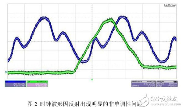
Due to the test at the midpoint of the signal link, the signal waveform will show a significant backlash due to reflection, and the back channel appears exactly in the middle of the rising and falling edges of the clock signal, which will give the clock and data. The timing measurement between them brings considerable instability, and the measured timing and actual conditions will also vary greatly. As shown in Figure 2 below, there is a significant monotonicity problem with the measured clock waveform.
Second, predict the waveform at the end of the memory through the virtual probe function
There are two ways to perform virtual probes in LeCroy oscilloscopes:
1. Channel simulation function using EyeDoctor II software
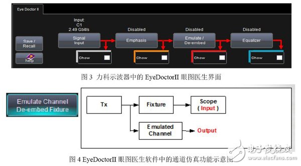
To use this method, you need to find the S-parameter from the test point to the end of the link, and then bring the S-parameter into the EyeDoctor II eye doctor software of the oscilloscope (as shown in Figure 3) to predict the waveform of the end signal. However, in practical applications, since the test point may be just a via, the test point is in the middle of the link, and the link cannot be broken into two parts from the test point position, so it is difficult to measure the test point position to the chain. The S parameter at the very end of the road. It is easier to extract the S parameters from the PCB through software, but the results of the simulation and the actual situation will still be different.
2. Use VP@Receiver virtual detection function in LeCroy oscilloscope
The basic principle of VP@Receiver is to obtain the delay Td of the transmission line from the test point to the end of the link, the matching model at the end of the transmission line (capacitance C, inductance L, impedance Z), and then apply these parameters to the measured waveform and The signal waveform at the end of the link is inferred. Let's take an example to illustrate how to use VP@Receiver to implement virtual probe function:
As shown in Figure 5 below, we can measure the signal waveform of point A by oscilloscope, and then we need to use this waveform to obtain the waveform of point B through virtual detection.
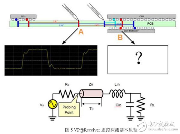
To obtain this waveform, we equivalent the transmission link between point A of test point and point B of the end of the link to the circuit model below Figure 5. The main parameters of the circuit model include link transmission delay T0, input terminal inductance Lin, input terminal capacitance Cin, and input terminal impedance RL.
Guangzhou Ehang Electronic Co., Ltd. , https://www.ehangmobile.com