
Laser diodes achieve stable light output with two common modes, constant power mode and constant current mode. The constant current mode is typically selected during testing because the constant current mode provides a faster control loop and a precise current environment for accurate current monitoring. This test method requires a source to provide a pulse or variable duty cycle current signal. The dynamic response of the test equipment must be accurately controlled. The current rise and fall speed must be fast enough. The current overshoot should be as small as possible. The good thing is to achieve negligence.
However, in general, customers will try to use the conventional high-power DC power supply to supply the energy required for laser diode testing, but since the conventional DC power supply is essentially a voltage source, its output current rises and falls when operating in constant current mode. The rate is limited and often cannot meet the needs of laser diode testing. And the transient response performance to achieve the design specifications needs to specify a load change of 30% to 50%. Considering that the inherent energy is stored in its output filter capacitor, usually at least 50% of the initial load is required. The slope of the current change provided by these power supplies is also ideally only on the order of tens of amps per millisecond, which is far from the requirements of laser diode testing. Therefore, we need a high-power current source to generate these fast current pulses to the laser diode to complete the test.
AMETEK's Sorensen brand SFA series power supply is such a unique product. It is a fast transient response current source product designed for high power laser driver applications, providing customers with a good solution for such testing.
The current rate of SFA power supply is much higher than other power supplies on the market because the current amplifier bandwidth used is much higher than the others, and its output filter capacitor is reduced by more than 10,000 times. The test current required for laser diode testing can be raised from zero to a very high value in a very short time.
We use a SFA60V/83A/5KW power supply for some verification tests. The test circuit is shown in Figure 1 to prove that SFA is the best solution for this type of test. The power supply uses constant current mode and uses an external pulse generator as the analog range source to control the pulse current required for the SFA output. The operation of this test scheme is simple, but the length of the cable should be considered as short as possible to reduce the effect of lead inductance on the current slope. We use an oscilloscope to capture the key parameters of rise and fall times.
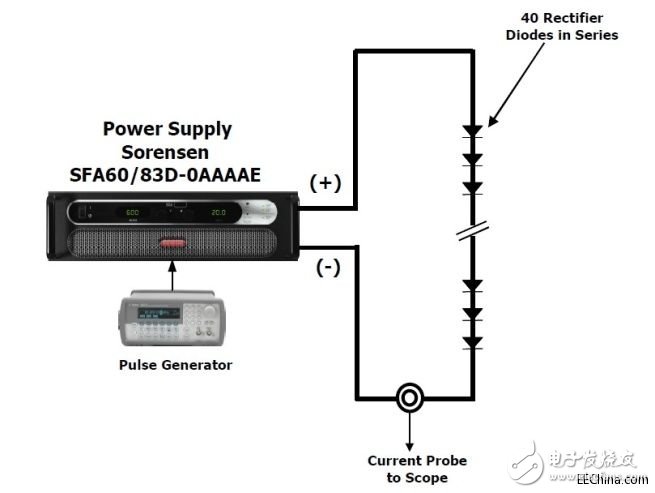
Figure 1. SFA60/83 current source and laser diode load
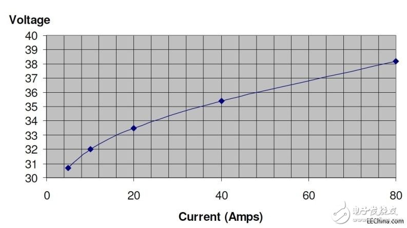
Figure 2, diode VI curve
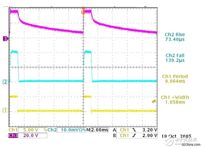
Figure 3, diode voltage (top), diode current (middle), programmable signal (bottom)
100Hz, 10% duty cycle, 50% current programming, current output rise time is related to voltage rise time, but much faster than voltage drop time because it is clamped by diode conduction voltage, so the current waveform is basically consistent with the program control signal.
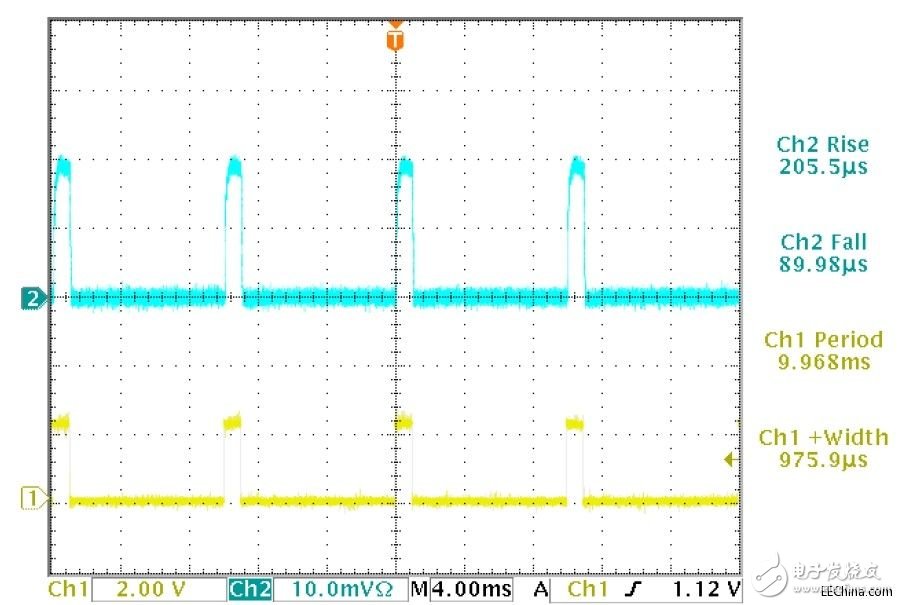
Figure 4, diode current (top) and program control signal (bottom)
100Hz, 10% duty cycle, 25% current programming output.
The current and the program control signal are very similar.
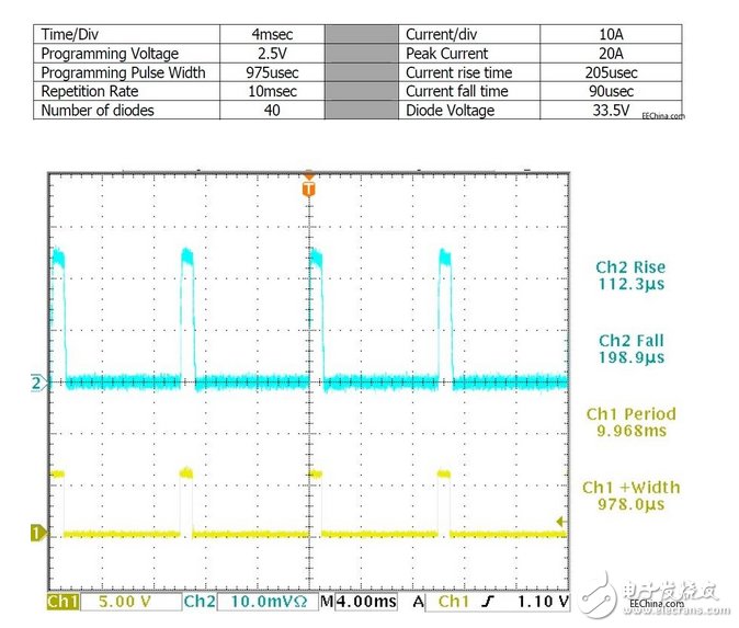
Figure 5, diode current (top) and program control signal (bottom)
100Hz, 10% duty cycle, 60% current programming output.
The current is very similar to the programming signal.
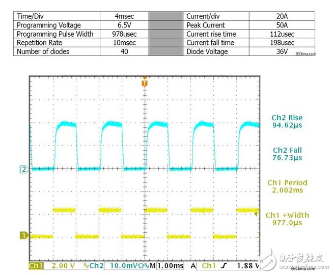
Figure 6, diode current (top) and program control signal (bottom)
500Hz, 50% duty cycle, 25% current programming output.
The current and the program control signal are very similar.

Figure 7, diode current (top) and program control signal (bottom)
500Hz, 50% duty cycle, 50% current programming output.
The current and program control signals are very similar, with a 50μs delay. Note that there is no overshoot at this time.
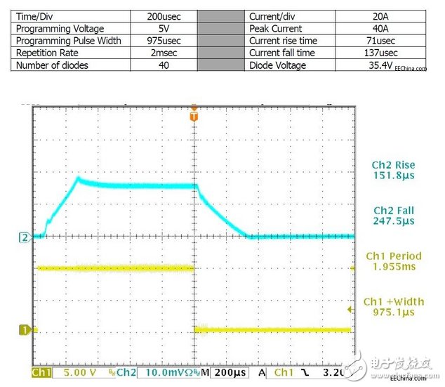
Figure 8, diode current (top) and program control signal (bottom)
500Hz, 50% duty cycle, 100% current programming output
The current and program control signals are very similar, with a 50μs delay. There is about 10% overshoot at this point because it already outputs the maximum current.
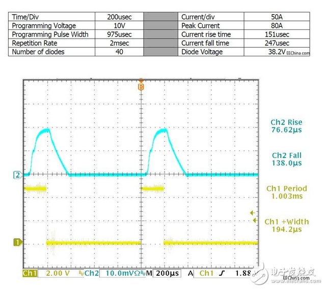
Figure 9, diode current (top) and program control signal (bottom)
Ningbo Autrends International Trade Co.,Ltd. , https://www.mosvapor.com