
In today's world with energy shortages and increasingly serious environmental pollution, how to effectively use clean solar energy is becoming a sustainable energy strategy for all countries. At present, most lighting equipment still uses traditional energy to illuminate, so making full use of solar energy as the energy supply of lighting equipment is of great significance in saving energy and protecting the environment.
For this reason, a metal halide lamp controller with solar power supply function is designed. The controller not only has the function of the metal halide lamp electronic ballast, but also has the function of the solar charger. As an electronic ballast, the controller has the advantages of high power factor, stable operation and small size compared with traditional ballasts. As a controller with solar power supply function, according to the setting, the controller controls the solar charging system to charge the 12 V/100 Ah battery during the day and makes the metal halide lamp work at night. As the solar photovoltaic panels are easily damaged by lightning in the natural environment, the controller is designed with the protection function against lightning strikes.
1 The overall structure of the controller
The controller uses a micro-packaged C8051F920 monolithic IC as the CPU, C8051F920 as a highly integrated (SoC), high-speed (100 MIPS) IC, which has the following characteristics:
(1) High-performance integrated analog peripherals. Generally, external analog components and system calibration and multi-channel high-speed sampling can be eliminated during data collection, which is conducive to power-saving design. At the same time, external clock devices can be omitted. The analog signal wiring has been completed on-chip, so the PCB design can be simplified and the noise performance of the system can be improved. It has a 10-bit resolution ADC and a high-precision internal oscillator (1.5%).
(2) External communication interface. One of UART, SM-Bus/12c, SPI can be selected as serial communication interface through software, with special serial interface USB 2.0, CAN 2. OB, 16-bit and 8-bit multiplexed and non-multiplexed parallel data bus.
(3) High-performance digital I/O. With counter/timer PCA module, I/O can be dynamically configured in real time.
The hardware structure block diagram of this controller is shown as in Fig. 1.
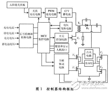
The solar photovoltaic panel is connected to the photovoltaic signal processing circuit, and the photovoltaic voltage is sent to the 12 V battery through the PWM charging control circuit. In normal operation, the output voltage of the 12 V battery is boosted and rectified by the secondary induction of the high frequency planar transformer to the full bridge circuit. At the same time, the 12 V output voltage is connected to the voltage conversion circuit to supply power to other circuits of the controller.
The full bridge drive circuit is connected with the ignition circuit and the metal halide lamp. The full bridge drive circuit uses UBA2032 chip. When the metal halide lamp is short-circuited, the full-bridge drive can be short-circuited to close the full-bridge. The keyboard and display man-machine interface can set the ignition time, mode, charging overvoltage protection range, etc. The boost rectifier circuit is connected with the switch control circuit to boost the input 12 V to 60-120 V for the metal halide lamp to work.
The MCU monitoring circuit is connected with the PWM charging circuit, the voltage conversion circuit, the full bridge drive circuit, the keyboard and the display man-machine interface, and controls the charging and discharging of the 12 V battery, the starting and stable operation of the ignition coil, the metal halide lamp, and the circuit protection. The ignition circuit rectifies the boosted negative voltage and forms a lighting voltage of 10-20 kV together with the lighting coil. The signal detection and conversion circuit has the function of detecting the current voltage and current of the 12 V battery, the battery charging current, and the voltage of the photovoltaic signal processing circuit.
2.1 Solar charging system
The charging system includes a photovoltaic signal processing circuit and a PWM charging control circuit. Figure 2 is a schematic diagram of the structure of the charging system.
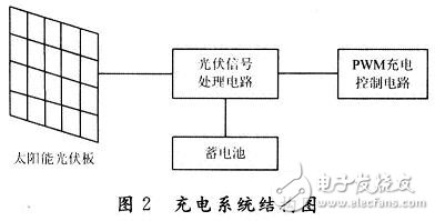
The photovoltaic signal processing circuit includes an anti-signal reverse connection circuit, a photovoltaic voltage sampling circuit and a lightning protection circuit. Among them, the anti-signal reverse circuit can prevent the photovoltaic signal reverse input from causing damage to the controller circuit. The voltage sampling circuit provides the photovoltaic voltage signal sampled by the C8051F920. The lightning protection circuit can prevent the lightning and lightning strikes in the sky from being introduced into the controller and causing damage. The PWM charging control circuit will charge the battery, and the PWM signal output by the MCU is used to drive the high-power MOS tube to control the charging voltage to avoid damage to the battery.
2. 2 electronic ballast circuit design
The boost rectifier circuit includes a flyback boost high frequency planar transformer, a fast recovery rectifier diode and a protection circuit. The primary of the high-frequency planar transformer is connected to the input end of the power supply and the power MOS tube, and the secondary is connected to the rectifier diode and the protection circuit. When the metal halide lamp is started, the secondary provides a DC voltage of about 400 V, which is transformed into a DC voltage of 1 200 V by a triple voltage rectifier circuit. During normal operation, the secondary of the transformer provides 60-120 V DC voltage. The boosted voltage signal is sent to C8051F920 through LM2902 to realize voltage sampling and detection.
Maskking High Gt,Maskking Coconut Ice,Masking High Pro,Disposable Vape Maskking
Shenzhen Zpal Technology Co.,Ltd , https://www.zpalvapes.com