
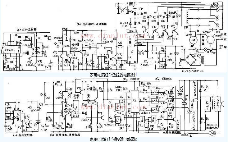
As shown in the figure, the household electric fan infrared remote control circuit. The remote controller includes a transmitter and two parts of receiving and controlling. The core of the infrared emitter is an astable multivibrator consisting of 555 and R1, W1, C1, etc., whose oscillation frequency is f=1.44/(R1+2Rw1)C1 and is adjusted at 38kHz to drive infrared emission. The diode HG310 or HG450 emits an infrared pulse. The infrared receiving tube should adopt the tube type matched with the transmitting tube, and pay attention to the optical wavelength and optical power when selecting.
IC1 uses the special infrared receiving integrated block μPC1373HA to tune the L and C4 loops at the center frequency of 38kHz. Once the infrared light pulse signal is received, the signal is amplified, detected and shaped by IC1, so that IC1 outputs a low level signal, correspondingly BG2 cutoff, the high level signal of the collector output is added to the clock input end of IC3, start counting, output the first high level pulse (Y1), make the electronic switch IC4-a, BG5 turn on, the thyristor SCR1 Turn on, the fan is energized, enter the "weak" wind operation state; after the next control signal arrives, output the second high-level pulse (Y2), so that the electronic switches IC4-b, BG6, SCR2 are turned on one after another, the fan enters "Medium" wind state; then enter the "strong" wind state; if there is a control signal coming, the fourth high-level pulse Y4 appears to the reset terminal, so that IC3 is cleared to 0, the counting stops, and the fan stops. When IC1 receives an infrared signal with a duration of about 5 seconds or more, pin 1 charges C6 because it is at a low level. When C6 is charged to a certain value, voltage regulator Dw breaks through and turns on, correspondingly makes BG3 tube When the conduction is turned on, the collector potential is increased, so that the bistable circuits IC2a ​​and IC2b are turned over, and the high level of the IC2b output causes the controllable oscillator composed of IC2c, IC2d, and Rm12, W1, C9, etc. to start. The BG4 tube is turned on-off-conducting with the level of the oscillation pulse, so that the three switches of the control IC4 (CD4066) are turned on and off in turn, and then. The thyristors SCR1, SCR2, and SCR3 are sequentially turned on and off to form a natural wind. Adjusting the potentiometer W1 can change the frequency of the IC2c and IC2d oscillators to make the natural wind effect better.
Educational projectors are mainly aimed at classroom teaching by school teachers; traditional projectors are not easy to carry. Due to the naughty students in school classrooms, projectors are not safe to place in classrooms and are easily damaged by students. The portability of educational micro-projectors makes up for teaching Vacancy, it is convenient for teachers to give lectures and only need to store the materials in the projector and show them to students for teaching, saving the trouble of textbooks and handwriting with pens and chalks. Its general weight will not exceed 0.2Kg, and some do not even need fan cooling or ultra-small silent fan cooling.
Educational projectors need to have:
1. Clear handwriting Educational projectors most often display text and images, at least a resolution of 1024*768 or more, and a contrast ratio of more than 3000 lumens, so that students in the back row can see the projection clearly
2. Short-focus large screen;
3. Accurate color;
4. Easy operation;
5. Features such as multiple connection methods.
education projector,education use projector,smart education projector,best education projectors,projector for education
Shenzhen Happybate Trading Co.,LTD , https://www.happybateprojectors.com