
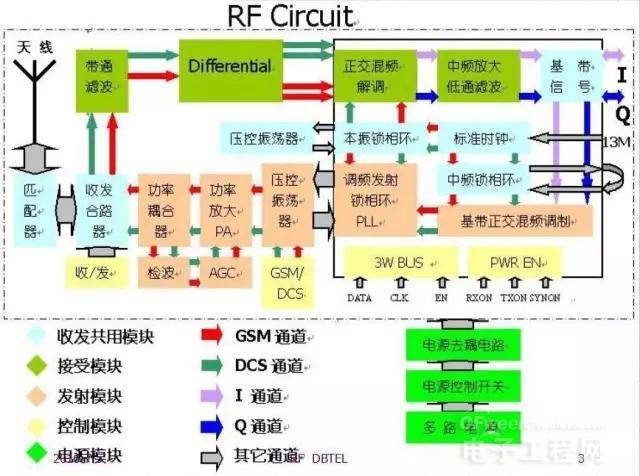
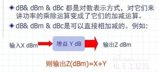
With the rapid development of circuit integration technology, RF circuits tend to be integrated and modular, which is particularly advantageous for the development and application of miniaturized mobile terminals.
At present, the RF circuit of the mobile phone is composed of a peripheral auxiliary and control circuit centered on the RFIC.
The analysis of the typical functional modules in the RF circuit is the main content of our discussion.
Outline
Transceiver
Phase-locked loop (PLL)
Power Control Loop (APC)
Transceiver duplexer (Diplexer)
Attenuation network
Matching network (Matching)
Filter network (Filter)
Balanced network (Balance)
other
1. Transceiver
Transceiver
Modulation: The baseband signal is loaded into the RF signal during transmission
Demodulation: RF signal is filtered out of the baseband signal during reception
Transceiver can be divided into: single frequency, dual frequency, triple frequency, etc. according to its working frequency.
Transceiver can be divided into medium frequency, zero intermediate frequency, near zero intermediate frequency, etc. according to the frequency characteristics.
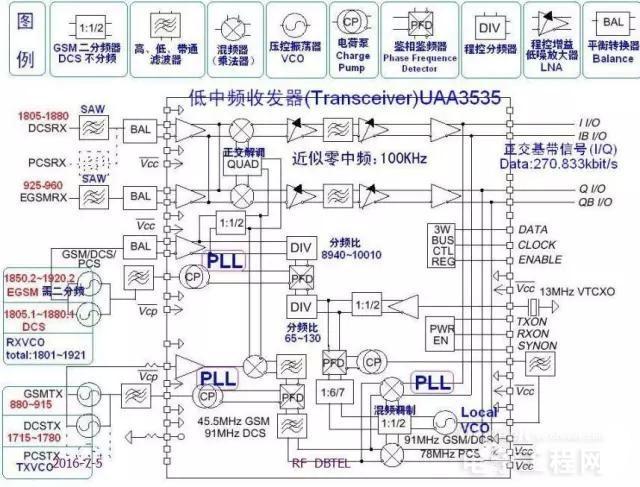
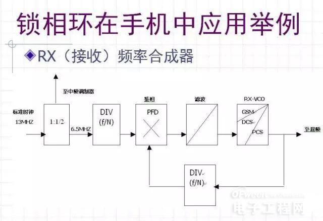
Introduce the internal structure of Transceiver UAA3535 with DB2009 as an example.
UAA3535 is a near zero IF transceiver, which can be used for up to three frequency transceiving
It has:
Three PLLs (including a built-in VCO), quadrature mixing demodulator, controllable gain low noise amplifier, mixing modulator, etc.
It needs to be external:
13MHz reference reference clock, RXVCO, TXVCO, baseband control signal, etc.
We need to study the frequency, bandwidth, signal conversion process and other details of its important internal nodes.
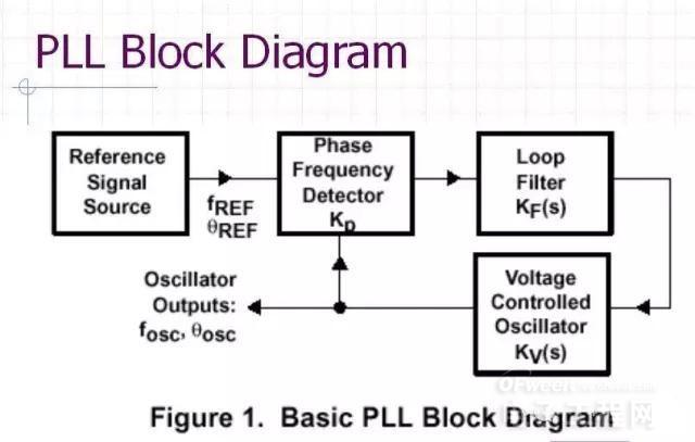
2. Phase-locked loop (PLL)
The four basic components of the phase-locked loop:
Phase detector (PD) discriminator (FD) phase discrimination (PFD):
PD/FD/PFD is a phase/frequency comparison device used to detect the phase/frequency difference between the input signal and the feedback signal.
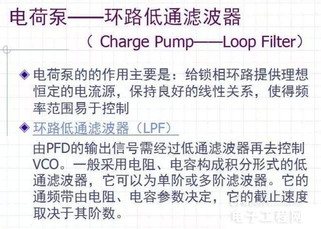
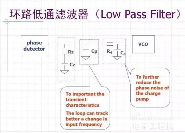
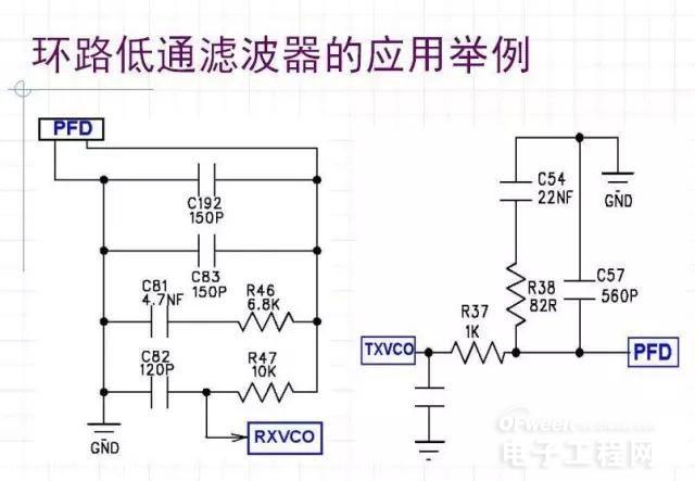
Loop Filter Loop Filter(LP):
LP is generally an N-order low-pass filter
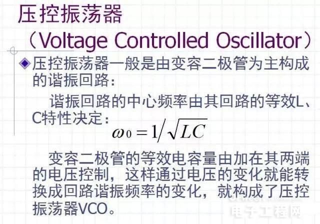
Voltage Controlled Oscillator (VCO):
The VCO is a voltage-frequency converter, and the output oscillation frequency should vary linearly with the input control voltage.
Reference signal source:
The reference signal source provides a contrast input signal for phase discrimination with the feedback signal
Phase-locked loop performance
The basic performance of the phase-locked loop includes the capture process and synchronization
(1) The performance of the capture process refers to the capture band and capture time.
The capture band refers to the maximum natural frequency difference allowed by the loop to enter the synchronization state through the capture process.
The capture time is the time interval between the start of the ring route and the time of entering the synchronization state.
Frequency deviation capability 》》 the max. PLL capture range
(2) After the loop is locked, the steady-state frequency difference is equal to zero, and the synchronization state is entered. The steady-state phase difference is usually always present and it is a fixed value.
Loop tracking performance
The faster the input signal changes, the worse the tracking performance will be. The magnitude of transient phase error and steady-state phase error is an important indicator to measure the performance of loop linear tracking.
Loop noise performance
Noise includes input noise and harmonic interference as well as internal noise and harmonic interference. Noise inside the voltage controlled oscillator is the main source of noise.
Loop capture performance
The wider the capture band, the shorter the capture time. The better the gain of the loop can be, or the bandwidth of the filter can be increased. However, increasing the loop gain or filter bandwidth is often related to improving the tracking performance and filtering performance of the loop. The requirements are contradictory. Auxiliary capture is used to achieve the goal. Including auxiliary frequency discrimination and frequency discrimination, variable bandwidth and variable gain.
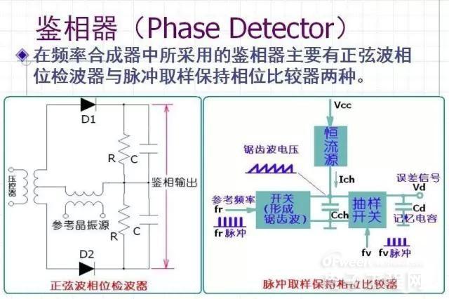
Basic component circuit analysis
Phase Detector
Charge Pump - Loop Low Pass Filter
(Charge Pump - Loop Filter)
Voltage Controlled Oscillator
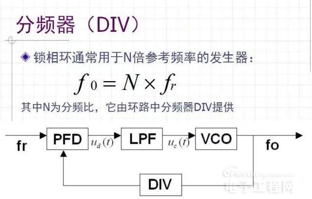
Divider (DIV)
VCO selection elements
High spectral purity
Linear voltage-frequency transfer characteristic
Good frequency stability to temperature
Frequency deviation capability 》》the max. PLL capture range
Time response
Low power consumption and Output level
Output harmonic level andtuning sensitivity
Phase noise
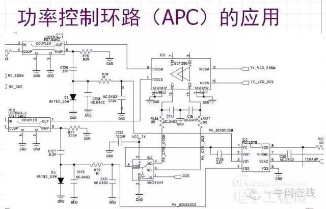
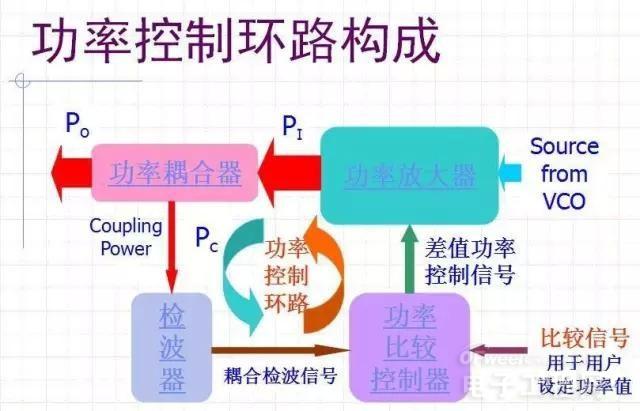
3. Power Control Loop (APC)
The power control loop consists of:
Power Amplifier
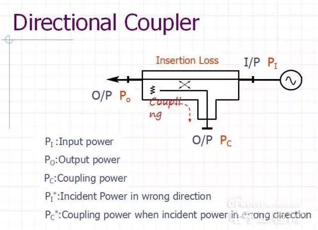
Power Coupler
Power Coupler
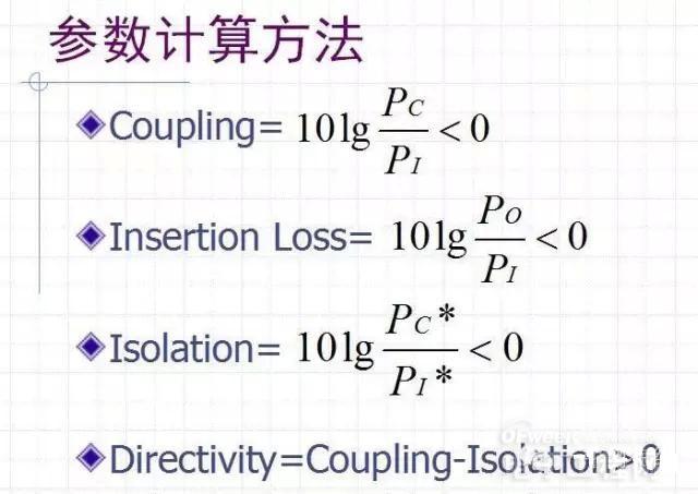
In order to achieve power control, the power sensor we need to use is the power coupler, which is generally a Directional Coupler.
Its main parameters are: see its LDC Data Sheet
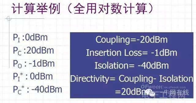
Coupling
Insertion Loss
Isolation
Directivity
[Unit (dB)]
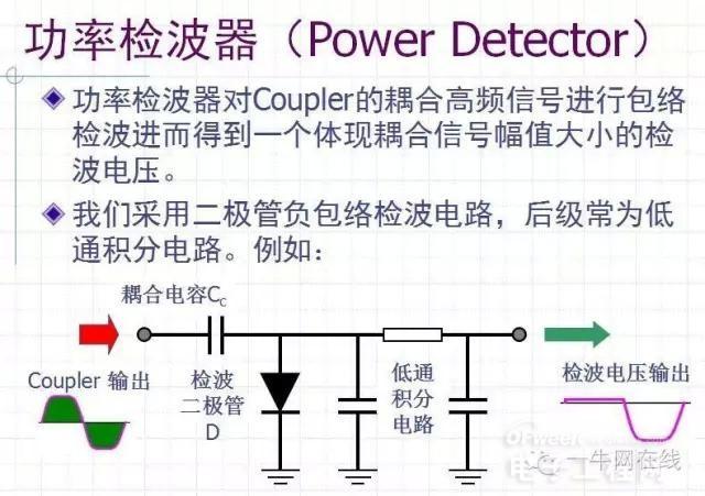
Negative envelope detection for diode requirements:
Detector diode D with P input
The pole capacitance of the detector diode requires a small Schottky diode. If the pole capacitance is too large, the coupling of the negative envelope will be lost to a low level, resulting in poor detection.
Power Detector
Power comparison, controller (Power Comparator & Controller)
The loop thus constructed can control the power more stably at our set value, which can be constantly changed as needed.
Power Amplifier
At present, PA for mobile phones is generally made of thick film analog circuit, which requires linearization of low-power RF signals without distortion to a certain power value.
Its main parameters are:
Working frequency and bandwidth;
Maximum linear output power (compression point);
Linear amplification for input power requirements;
Input and output required matching impedance;
Working power and voltage and current requirements;
The form and requirements of the control signal;
Noise characteristics and more.

The 60W Macbook Charger with MagSafe1 or Magsafe 2 Power Adapter has a magnetic DC connector, so if someone trips on it, the power cord disconnects harmlessly, keeping your MacBook Air safe. It also helps prevent the cable from fraying or weakening over time. Additionally, the magnetic DC helps guide the plug into the system for a quick and safe connection.
60W Apple charger usb c,60w charger macbook air,macbook 60w charger
Shenzhen Waweis Technology Co., Ltd. , https://www.waweisasdapter.com