
In order to improve system communication efficiency and reduce costs, all current automotive designs use a large number of serial bus communication protocols. The I2C and SPI protocols are typically used for inter-chip communication in electronic control units (ECUs). For long-distance serial communication and control between various automotive subsystems such as comfort control systems, anti-theft locks, drivetrains and engine controls, the CAN, LIN and FlexRay protocols are the most common serial buses in the automotive industry today. application.
LIN serial buses based on master-slave relationships are primarily used for applications where security is not critical, such as seat and window control. The CAN serial bus uses differential event triggering, which has higher noise immunity than the single-ended LIN bus and has been used as the main control bus for automobiles for more than two decades. The FlexRay serial bus uses differential time triggering and a synchronous deterministic schedule. As an emerging serial bus technology, FlexRay is used in some high-end vehicles, mainly for systems with high performance and security requirements.
However, serial bus communication is often affected by signal integrity issues caused by non-ideal environments inside the car, including signal interference from the ignition system and random system noise, which sometimes creates errors in critical communication cycles. Although the Serial Bus Protocol Analyzer is ideal for testing and monitoring the transmission of serial bus data at higher protocol layers and application layers, they cannot measure the integrity/quality of your car's serial bus signal (physical layer).
Some current mid/high performance digital storage oscilloscopes (DSOs) provide LIN, CAN, and FlexRay bus decoding and triggering capabilities to establish time-correlated links between the protocol layer and the physical layer.
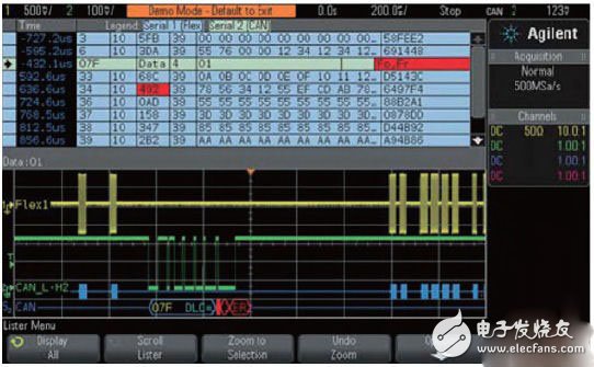
Figure 1 shows the Agilent 3000 X-Series oscilloscope simultaneously capturing and decoding CAN and FlexRay buses. At the bottom of the display is the time-correlated decoding trace for each bus, located below the captured physical layer waveform. The top half of the oscilloscope display shows the industry's only time-crossing "list" display, sometimes called an event table. This data format is closer to the traditional protocol analyzer.
Stack Battery,Saft Lithium Batteries,Stacked Lithium Battery,Solar Lithium Battery
JIANGSU BEST ENERGY CO.,LTD , https://www.bestsolar-group.com