Urban roads are intricate and intertwined, and traffic lights are an important command system for urban traffic. As an effective means to control traffic flow and improve road traffic capacity, traffic lights have obvious effects on reducing traffic accidents. However, the traffic volume is changing at any time, while the traditional traffic light mode uses timing control, which is easy to cause traffic jams. Therefore, designing a simulation and design of a traffic light control system based on Proteus and single-chip microcomputer is of great practical significance for reducing traffic accidents, alleviating traffic congestion and improving the smoothness rate.
1, system designThe east, west, and north roads intersect at a crossroad. Each road has a set of traffic lights. Each state has a set of red and green lights. That is, a group of traffic lights have left turn, straight turn, and right turn to three sets of red. A green light and a yellow light indicate the safe passage of vehicles and pedestrians. The red light is forbidden to pass, and the green light is allowed to pass. The yellow light flashes to remind people that the traffic light status is about to switch.
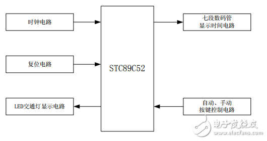
1.1, the design of the system hardware circuitThe use of single-chip design and application system should consider the hardware circuit to be as simple as possible, and to maximize the functions of the system. Therefore, this paper uses STC89C52 single-chip microcomputer as the control core to design the control system of traffic light. In this system, the STC89C52 and each module of the peripheral circuit exchange information and control accordingly. The system block diagram is shown in Figure 1.

Figure 1 block diagram of the traffic light system
The system consists of clock circuit, reset circuit, control system circuit, LED traffic light display circuit, seven-segment digital tube display time circuit, automatic and manual button control circuit. The main controller uses STC89C52 microcontroller. P1 port is set to red, green light and yellow light flashing, P0, P2 port to display time, P3 port to set system working mode. The red, green and yellow lights of the traffic lights are realized by light-emitting diodes, and the time display is realized by a seven-segment digital tube.
1.2, the design of the system software circuit1) LED traffic light display module
The 89C52 single-chip P1 port controls the LED traffic light, and controls the corresponding LED traffic light status in different states.
2) Digital tube display module
89C52 single-chip microcomputer P0 port time countdown period selection, P2.0~P2.3 ​​port for digital tube time display bit selection, use T2 interrupt timing to refresh the seven-segment digital tube every 2ms.
3) Keyboard control module
89C52 single-chip P3.0~P3.3 port and P3.6 port external keyboard control traffic lights automatically and manually state and manual control different states for real-time scanning, enter the corresponding operating state.
2, system working mode 2.1, automatic control modeThe system is started in automatic control mode. Initially, it is a green light when the north-south direction is turned on, and the rest is a red light, and the digital tube counts down from 15s. When the countdown reaches 8s, the yellow light starts to flash (1s finishes flashing once), after 3s flashing, it counts down to 5s. Turn left and right in the north-south direction to green light, straight behavior red light; when the countdown reaches 0s, the intersection enters the forbidden waiting state, that is, the green light is all off and the red light is on, and the digital tube starts counting from 3s, and the yellow light starts. Flashing 3s; when the countdown is 0s again, after the yellow light flashes, the north-south digital tube counts down from 18s, while the east-west direction is green, the rest is red, and the digital tube counts down from 15s, when the countdown is At 8s, the yellow light starts to flash (1s finishes flashing once). After 3s flashing, that is, when it counts down to 5s, the east-west direction turns left and right turns to green light, and the straight behavior is red; when the countdown reaches 0s, the intersection enters the forbidden waiting state. , that is, the green light is all off, the red light is on, and the digital tube counts down from 3s, and the yellow light starts to flash for 3s; when the countdown is 0s again, the yellow light flashes. East-west direction from the digital countdown beginning 18s, while the north-south direction straight ahead is the green light turns on, and the rest is red, and from the beginning of 15s digital countdown cycle in this way.
2.2, manual control mode1) When the system is working in the automatic mode, if the manual control button currently in the on state is pressed, the system directly enters the conduction state, and the digital tubes in the north-south and east-west directions display 99; if the pressing is not currently in progress When the manual control button is turned on, the system will perform a 3s yellow light flashing countdown state for the currently being turned on state. When the countdown is over, the system will enter the conduction state of the pressed key, and the north-south and east-west directions. The digital tube displays 99; when the rest of the manual control buttons are pressed, the system will enter the conduction state of the pressed key.
2) When the system is working in the manual mode, if the automatic control button is pressed, the system will perform a 3s yellow light flashing countdown state for the currently being turned on state. When the countdown is over, the system will enter the initial automatic control mode.
3) When the system works, if the system is in the north-south direction, when the north-south crosswalk is turned on, people can cross the crosswalk in the east-west direction through the crosswalk; similarly, if the system is in the direction of the east-west direction, At this time, the crosswalk in the east-west direction is turned on, and people can cross the crosswalk in the north of Vietnam through the crosswalk.
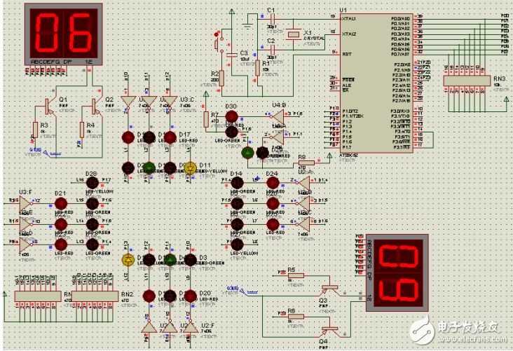
3, Proteus simulation designThrough the Proteus software, the system hardware design and software design are combined with simulation. The program code is compiled and compiled by Keil to generate HEX file, and then the program is loaded by clicking the MCU to realize the combined simulation of hardware and program. The system simulation results are shown in Figure 2.

Figure 2 Simulation results based on Proteus and Keil
The traffic light control system designed in this paper takes the single-chip STC89S52 as the main controller, draws the hardware circuit with Proteus software, uses Keil for programming, and then performs integrated simulation to realize the predetermined function. The system is respectively equipped with three traffic lights for control in each road, that is, north-south and east-west direction, that is, left turn traffic light, straight traffic light, right traffic light, and three traffic lights in each direction run simultaneously. In addition, the system also has two modes: automatic and manual. In general, the system runs in an automatic state. If the traffic is at a peak, the traffic police will conduct traffic diversion. At this time, the traffic police The system can be switched to manual mode to divert traffic, especially for bad weather conditions such as hot and rainy weather. The system has strong practicability, relatively simple operation, strong expansion function, low cost and low power consumption, and has a very wide application prospect.
The LGF is extremely thin so it can be incorporated into Membrane Switches that can`t exceed a certain thickness (i.e., small, lighter devices) LGF has limited impact on the tactile feel of buttons. LGF can provide even backlighting across large and small areas, including applications where the light remains on while the switch is powered.
Lgf Membrane Switches,Control Panel Lgf Membrane Switches,Lgf Membrane Switches Keypad,Lgf Membrane Key Switch Panel
KEDA MEMBRANE TECHNOLOGY CO., LTD , https://www.kedamembrane.com
