It refers to a device that operates in the microwave band (frequency of 300 to 300,000 MHz) and is called a microwave device. Microwave devices can be classified into microwave oscillators (microwave sources), power amplifiers, mixers, detectors, microwave antennas, and microwave transmission lines according to their functions. Through circuit design, these devices can be combined into various microwave circuits with specific functions, for example, using these devices to assemble into transmitters, receivers, antenna systems, displays, etc., for use in radar, electronic warfare systems, and communication systems. equipment.
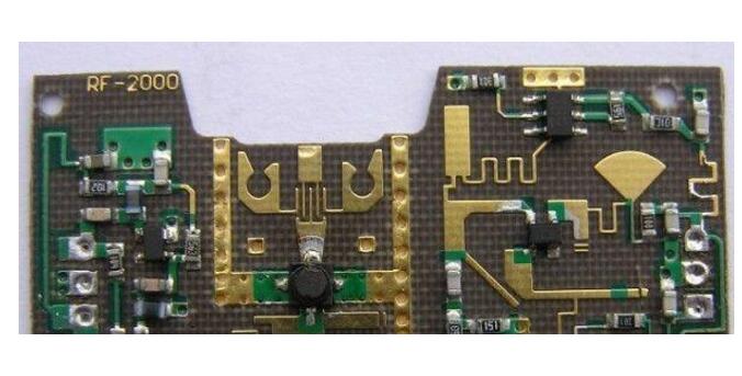
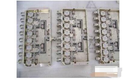
Microwave devices can be divided into microwave electric vacuum devices, microwave semiconductor devices, microwave integrated circuits (solid state devices) and microwave power modules according to their working principles and materials and processes. The microwave electric vacuum device includes a klystron, a traveling wave tube, a magnetron, a return wave tube, a gyrotron, a virtual cathode oscillator, etc., and uses electrons to move in a vacuum and interact with peripheral circuits to generate oscillation, amplification, mixing, and the like. Various functions. The microwave semiconductor device includes a microwave transistor and a microwave diode, and has the advantages of small volume, light weight, good operability, power consumption, etc., but cannot completely replace the electric vacuum device under high frequency and high power conditions. Microwave integrated circuits are fabricated on a gallium arsenide or other semiconductor material chip by a semiconductor process with microwave function to form functional blocks in solid phased array radar, electronic countermeasure equipment, missile electronic equipment, microwave communication systems, and ultra high speed. Computers have broad application prospects.
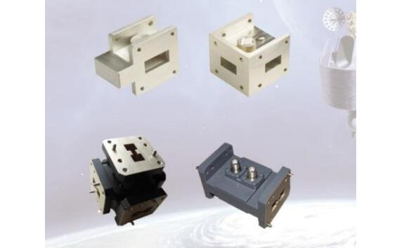
1. Terminal load component: a port reciprocal component, mainly including short-circuit load, matched load and mismatched load
1) Short-circuit load, requirements:
(1) Ensure that the loss at the contact is small,
(2) When the piston moves, the contact loss changes little;
(3) At high power, there should be no sparking between the piston and the waveguide wall.
Can be used as a dispenser, pure reactance component
Structure: contact, turbulent (metal)
2) Matching load
The main technical indicators of all components that absorb input power: operating frequency f, input standing wave ratio, power capacity. As a matching standard, equivalent antenna, absorption load, and the like.
3) Mismatched load
As a standard mismatch load. Absorb a portion of the power and reflect a portion of the power.
2. Microwave connection component: two-port reciprocal component. Mainly include: waveguide connectors, attenuators, phase shifters, and adapters. The role is to connect differently acting microwave components into a complete system.
The basic nature of the lossless reciprocal two-port network:
1) If one port matches, the other port automatically matches;
2) If the network is completely matched, it must be completely transmitted, or vice versa;
3) Only two of the phase angles of S11, S12, and S22 are independent. When two phase angles are known, the third phase angle can be determined.
3. Impedance matching components
Diaphragm (inductive diaphragm b side)
Capacitive diaphragm (wide side)
Pin (inductor)
Screw adapters (single, double, triple, and four screws----the same principle as the branch adapter, but the screws are only capacitors).
The device formed by the combination of solid-state microwave power devices has the advantages of high efficiency and convenient use, and is of great significance for achieving full solidification of electronic equipment such as radar, communication, and electronic countermeasures. Microwave oscillators (microwave sources) are important components in microwave systems and are the heart of electronic equipment, with a direct impact on their performance. For example, in a high-power microwave weapon system, a high-power microwave oscillator determines its killing performance; in a radar system, the microwave oscillator determines the range of the radar.
Application of Microwave Switch in Automatic Test of Microwave Passive DevicesTest passive components mainly use the appropriate network analyzer to test the S parameters of each port, such as insertion loss, isolation, return loss and so on. Let's take the test example of the isolator. The test procedure is as follows.
step 1:
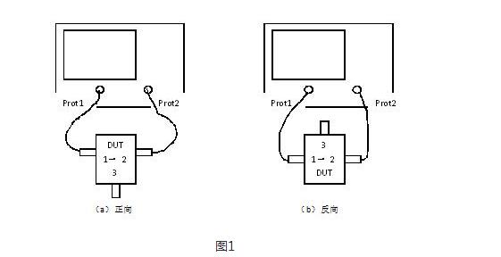
Test the DUT (forward) 1→2 return loss/standing wave (S11, S22), insertion loss (S21), isolation (S12), and 3-port with 50Ω load, as shown in Figure 1(a).
Test DUT (reverse) 1 → 2 return loss / standing wave (S11, S22), insertion loss (S12), isolation (S21), 3-port 50Ω load, as shown in Figure 1 (b).
Step 2:
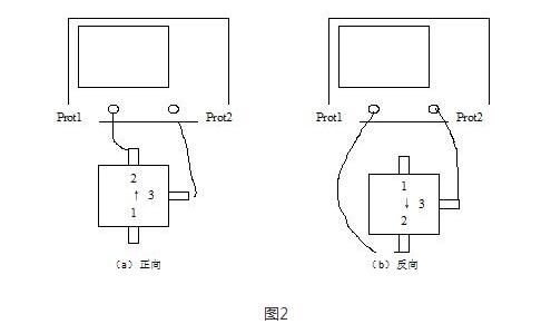
Test 2 → 3 return loss / standing wave (S11, S22), insertion loss (S21), isolation (S12) of DUT (forward), and connect 1 port to 50Ω load, as shown in Figure 2(a).
Test DUT (reverse) 2 → 3 return loss / standing wave (S11, S22), insertion loss (S12), isolation (S21), 1 port connected to 50Ω load, as shown in Figure 2 (b).
Step 3:
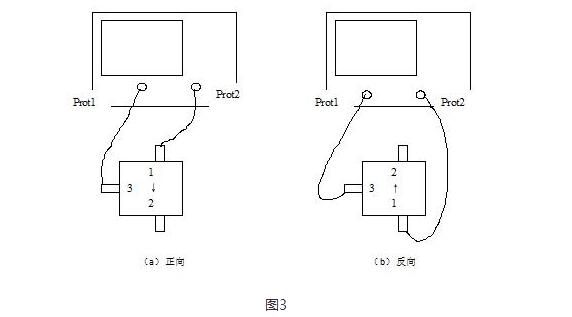
Test DUT (forward) 3→1 return loss/standing wave (S11, S22), insertion loss (S21), isolation (S12), and 2-port with 50Ω load, as shown in Figure 3(a).
Test DUT (reverse) 3 → 1 return loss / standing wave (S11, S22), insertion loss (S12), isolation (S21), 2 port connected 50Ω load, as shown in Figure 3 (b).
The above is all the steps to test an isolator. The test process is cumbersome. It is necessary to repeatedly connect the various ports of the isolator with a coaxial RF cable. Repeated insertion and removal can easily cause wear of the RF connector and increase the uncertainty of the test.
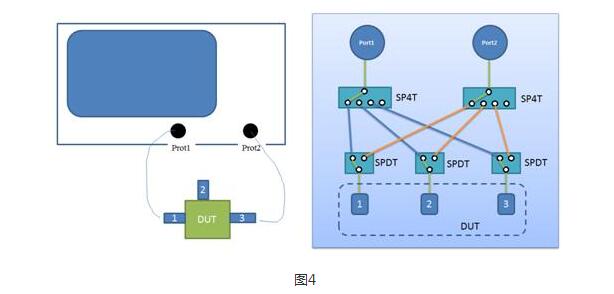
In fact, the idea of ​​automated testing is also applicable to the microwave industry. The key is to require reliable microwave devices, so Keysight's microwave switch plays a key role in this. Because Keysight's microwave electromechanical switches are not only low cost, but also have many superior performances. After two or five million uses, the insertion loss can be guaranteed to be less than 0.03dB, long working life, high isolation and low. SWR can minimize the uncertainty of the test. Especially in the test of high isolation filter, only the Keysight L7104A (SP4T) and 8762A (SPDT) are used to simply complete the isolator test process just given by us. As shown in Figure 4, by adding SP4TL7104A and SPDT8762A between the DUT port and the network sub-port, it is possible to completely measure the above three steps without inserting and removing the coaxial cable at one time.
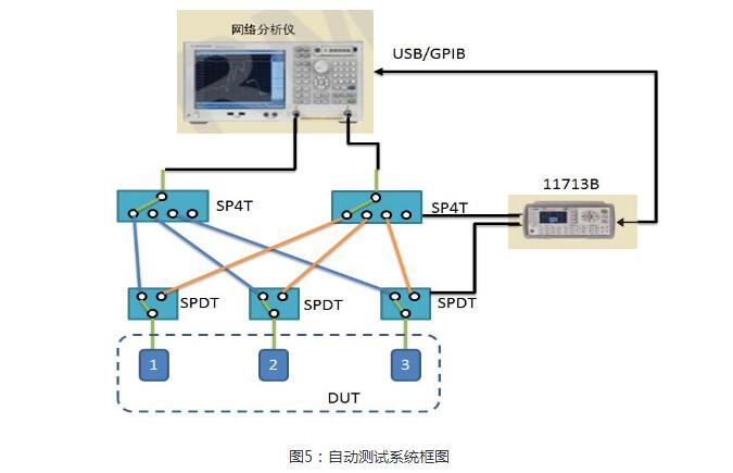
Microwave switches are also simple in terms of control. Keysight offers specialized switch drivers such as attenuator/switch driver 11713B/C for programmable attenuators, electromechanical or solid state switches for software programming or front panel drive control. Designed with both bench and ATE environments in mind, these attenuator/switch drivers provide an intuitive user interface for quick and easy design verification and automated testing, a variety of switching options, software programming capabilities, and A remote control feature. So building an automated microwave RF test platform is also a matter of minutes! As shown in the figure, Figure 5 below is a block diagram of an automatic test system for automatic test isolators or circulators.
Our Professional 100W solar panel manufacturer is located in China. including Solar Module. PV Solar Module, Silicon PV Solar Module, 100W solar panel for global market.
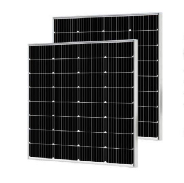
100W solar panel, Solar panel, PV solar panel, Silicon solar panel 100W
Jiangxi Huayang New Energy Co.,Ltd , https://www.huayangenergy.com
