
A voltmeter is an instrument for measuring voltage. A commonly used voltmeter, the voltmeter, has the symbol "V". The conventional pointer voltmeter includes a sensitive galvanometer. There is a permanent magnet in the sensitive galvanometer. A coil composed of a wire is connected in series between the two terminals of the galvanometer. The coil is placed in the magnetic field of the permanent magnet, and It is connected to the pointer of the watch by the transmission. Most voltmeters are divided into two ranges. The voltmeter has three terminals, one negative terminal and two positive terminals. The positive pole of the voltmeter is connected to the positive pole of the circuit, and the negative pole is connected to the negative pole of the circuit.
principle
Traditional pointer voltmeters and ammeters are based on one principle of the magnetic effect of current. The larger the current, the larger the magnetic force generated. The greater the swing of the pointer on the voltmeter, the more the voltmeter has a magnet and a wire coil. After passing the current, the coil will generate a magnetic field. Deflection occurs under the action of a magnet, which is the head portion of the ammeter and voltmeter.
Since the voltmeter should be connected in parallel with the resistance to be measured, if the galvanometer is used directly as the voltmeter, the current in the meter is too large, the meter will be burned out. In this case, a large resistor is connected in series in the internal circuit of the voltmeter. After this transformation, when the voltmeter is connected in parallel in the circuit, the voltage applied to both ends of the meter is mostly shared by the series resistor due to the action of the resistor, so the current through the meter is actually small, so Can be used normally.
The symbol of the DC voltmeter should be added with a "_" under V, and the symbol of the AC voltmeter should be followed by a wavy line "~".
structure
The voltmeter is a large resistor and is ideally considered to be an open circuit. In the parallel circuit, the voltmeter (in parallel with other electrical appliances) and the electrical appliance are connected in parallel. If there is no other electrical appliance in the trunk circuit, it can be considered that the power supply voltage is measured (because the electrical appliances on the parallel circuit all enjoy the voltage of the power supply) ); if other electrical appliances are connected to the main road, then the electric appliance shares part of the power supply voltage, and the voltmeter can only measure part of the voltage (which appliance is the voltage of which electric appliance is connected).
It should be known that in the voltmeter, there is a magnet and a wire coil. After passing the current, the coil will generate a magnetic field, so that the coil will be rotated under the action of the magnet after energization. This is the meter part of the ammeter and the voltmeter.
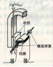
The current that this meter can pass is very small, and the voltage that can be withstand at both ends is also very small (certainly far less than 1V, may only be zero or several volts or less). In order to measure the voltage in the actual circuit, it is necessary to give This voltmeter is connected in series with a relatively large resistor to make a voltmeter. Thus, even if a relatively large voltage is applied to both ends, most of the voltage acts on the added large resistor, and the voltage on the meter head is small. A voltmeter is an instrument with a large internal resistance and should generally be larger than a few thousand ohms. The meter head is made up of the magnetic field force in the magnetic field according to the energized conductor. Inside the watch, there is a permanent magnet, which generates a magnetic field between the poles. There is a coil in the magnetic field. Each end of the coil has a spring spring. The springs are connected to a terminal of the watch. The spring and the coil are connected by a rotating shaft, and the rotating shaft is opposite. At the front end of the ammeter, there is a pointer. When a current passes, the current passes through the magnetic field along the spring and the rotating shaft, and the current cuts the magnetic induction line. Therefore, the magnetic field force acts to deflect the coil and drive the shaft and the pointer to deflect. Since the magnitude of the magnetic field force increases as the current increases, the magnitude of the current can be observed by the degree of deflection of the pointer.
How to judge the measurement object of the voltmeter1, short circuit method
The voltmeter is removed, assuming that the wire is connected to the position. If some electrical appliances or power supplies are short-circuited at this time, these electrical appliances or power supplies are the objects of the voltmeter measurement.
2, the source method
"Remove" the power supply (hold the power supply by hand), and then see which part of the voltmeter forms a closed loop, then the voltmeter measures the voltage of that part of the circuit.
3, slip line method
Both ends of the voltmeter slide along the connected wires to the ends of the appliance or power supply. (Can cross components: switches, ammeters. Can not cross components: power supply, electrical appliances, voltmeters.)
Special Instructions
1. The voltmeter is connected to the circuit and is equivalent to the open circuit.
2. The current meter is connected to the circuit as a wire.
3. The voltmeter and the electrical appliance are connected in series and then connected to the two ends of the power supply. The voltmeter measures the power supply voltage.

Judging whether the voltmeter measures the voltage of the part of the circuit, such problems frequently appear in practice and test questions. Because the voltmeter is connected in parallel with the electrical appliance, in the series circuit, whether it is a physical circuit or a circuit diagram with a change in form, the student It is often impossible to quickly and accurately determine which part of the voltage is being measured by the voltmeter. Based on the above reasons, the following methods, examples and exercises are given, hoping to give inspiration to students who have difficulty answering such questions.
In the series circuit, the following ideas and methods can be used to quickly and accurately determine which part of the circuit voltage is measured by the voltmeter:
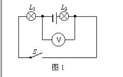
Example 1: The circuit shown in Figure 1: The voltage of the power supply is 6V. After the switch S is closed, the voltmeter detects ( )
A. The voltage across L1 is B. The voltage across L2 is C. The total voltage across L1 and L2 is D. Voltage across the power supply
Analysis:
Method 1: Think of the voltmeter as a "branch" of the circuit, find the two points connected to the voltmeter and use them as nodes. Except for the voltmeter, the original circuit is divided into two parts, which are regarded as parallel with the voltmeter. In the circuit, there is a bulb L2 and a power supply, and the other part only contains L1. The voltmeter measures the voltage across the circuit that does not contain the power supply, that is, the voltage across L1.
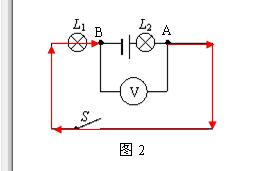
Method 2: As shown in Figure 2, find the two points connected to the voltmeter. Starting from the positive point of the power supply (point A), follow the direction of current flow and go to another point near the negative pole of the power supply (point B). With L1 on some lines, the voltage across L1 is measured.
Example 2: As shown in the circuit of Figure 3, the connection mode of the bulbs L1 and L2 is connected, the voltage meter V1 measures the voltage, and the voltmeter V2 measures the voltage.
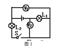
Analysis: When judging the circuit, the voltmeter is regarded as an open circuit, and is directly removed from the circuit. It can be seen that the lamps L1 and L2 are connected in series, the voltmeter V1 is connected in parallel with the bulb L2, and the voltage across the L2 is measured, and the voltmeter V2 is connected in parallel with the bulb L1. Measure the voltage across L1.
Our company provied many kinds of garden speaker,which has the characteristics of exquisite and lively shape, excellent sound playback effect, etc.The glass reinforced plastic simulation technology carefully designed and made, durable, realistic appearance, can be a genuine effect.It is suitable for use in outdoor environments to play excellent background music and voice playback functions.
Garden Speakers,Outdoor Speakers,landscape speakers,Rock Speakers,lawn speaker
Taixing Minsheng Electronic Co.,Ltd. , https://www.ms-speakers.com