
Inverter panel key description
Montr: Selection of monitored items
Accel: acceleration time
Decel: errand time
Vmtr: motor rated voltage setting/reference
V/F: V/F value setting reference
Fgain: Setting/reference of frequency command gain
Fbias: Setting/reference of frequency command bias
FLA: Setting/reference of motor rated current
PID: PID control logic
Kwsav: Energy saving mode ON/OFF
PRGM: parameter constant setting
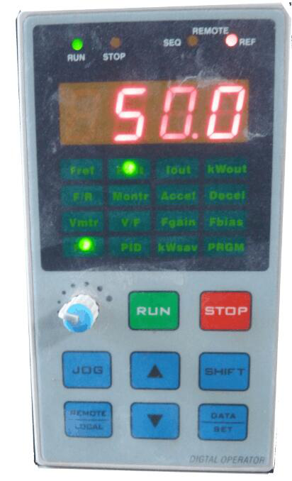
V/F: The V/F control of the inverter is a control method of the inverter. It is below the reference frequency. The output voltage of the inverter is proportional to the output frequency. A control method for outputting constant torque is the most The basic control method, there is a curve in the V/F change process, corresponding to different occasions, the V/F curve is also different, the intermediate electric music and the intermediate frequency in the corresponding VIF curve change process can be recorded in the inverter parameters set up. RUN: run
STOP: stop Local: local control
SHIFT: switch
JOG: Jog
SET: set
SEQ: Lights up when the run command input from the control circuit terminal is valid.
REMOTE: remote control
REF: Lights up when the frequency command input from the control circuit terminal is valid
Fref: Setting/monitoring frequency command
Fout: monitor output frequency
lout: monitor output current
kWout: output power
F/R: Setting/reference of running direction
Inverter panel key description
1: Change direction. Press this key to change the direction of rotation of the motor.
2: Start the inverter.
3: Stop the inverter operation.
4: The motor is jogging. When the inverter has no output, pressing this key will start the motor and run at the preset jog frequency. When this key is released, the inverter will stop running.
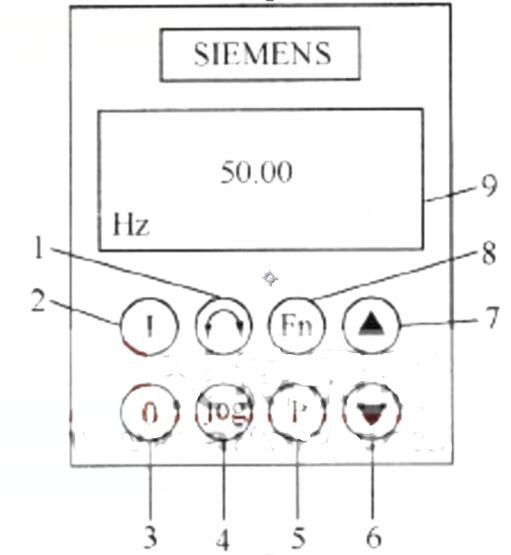
5: Access parameters. Press this key to access the parameters of the inverter.
6: Decrease the value. Press this key to decrease the value displayed on the panel.
7: Increase the value. Press this key to increase the value displayed on the panel.
8: This key is used to browse auxiliary information. Press this key and keep it still, and start browsing from any parameter during operation. The displayed data include DC link voltage (indicated by d), output current (A), output frequency (Hz), and output voltage (0) , P0005 selected value.
9: Status display. Display the setting value currently used by the inverter.
FR-DU04 Mitsubishi inverter panel description
Key functions of the operation panel:
1) MODE key: Used to select operation mode or setting mode. There are 5 working modes of the inverter: monitoring, frequency setting, parameter setting, operation and help mode. Press the MODE key, the working mode will be in sequence in the above 5 working modes, and the corresponding operation interface will be displayed on the display.
2) SET key: used to determine the frequency and parameter settings; in "monitoring mode", press the SET key, you can choose to display the operating frequency of the motor (Hz light on), operating voltage (V light on) or operating current (A light on) .
3) Up/down keys: used to increase or decrease the operating frequency and select the set parameters and values.
4) FWD key: used to give forward rotation command.
5) REV key: used to give reverse instruction.
6) STOP key: used to give a stop instruction; or reset the inverter when the protection function action output stops (mainly used for fault reset)
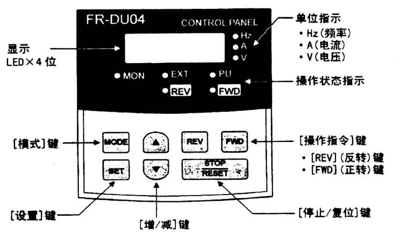
The operation status of each indicator on the panel shows:
1) Hz: lights up when the frequency is displayed;
2) A: Lights up when displaying the running current of the motor;
3) V: Lights up when displaying the motor operating voltage or program running display time;
4) MON: Lights up when the monitor mode is displayed;
5) PU: On in PU operation mode; 6) EXT: On in external operation mode;
7) FWD: flashes when the motor is running forward;
8) REV: flashes when the motor is running in reverse.
Magnetic Core,Soft Iron Powder Core,Ac Flux Iron Powder Core,Epoxy Coated Iron Powder Core
Shaanxi Magason-tech Electronics Co.,Ltd , https://www.magason-tech.com