
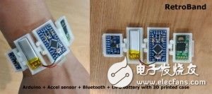
The "Retro Bracelet" is the second edition of the open source Arduino wearable device. In my case, this shouldn't be called a "smart bracelet", it's just a simple function. In fact, it is better to call it an activity tracking recorder...just the word "smart bracelet" is more intimate to me. An important feature of smart bracelets is that they can connect to mobile devices via Bluetooth and record user work schedules.
Arduino's retro bracelet has a single function, which collects data through an accelerometer and sends it to the mobile device. The mobile device calculates the user's calories burned and walking steps based on the data. The function is very simple, which means that the structure of the device is simpler than the previous "retro watch", so it is easy to make according to your personal taste.
The Android app uses the Arduino retro bracelet feedback to calculate the number of walking steps, and the applied algorithm is not complicated. If you have a lot of experience with the algorithm, you can use your own algorithm instead. The mobile app stores calorie data so you can get a monthly/daily/hourly chart report. But to be reminded, the Arduino retro bracelet has very little memory and can't store information on its own. It can only work on mobile devices, which means you can't collect data by Arduino retro bracelet alone. I think this problem will be solved well after the Arduino improvement.
The first step: working mechanism
The vintage bracelet consists of the Arduino part and an Android app.
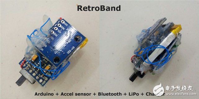
The Arduino section is divided into four main sections - the Arduino board, the accelerometer (MPU-6050), the Bluetooth module (HC-06), and the polymer lithium battery (optional for the charging board).
The Android app also includes 4 parts - Android interface, Bluetooth management, algorithm part, background service.
If the Arduino is powered on and paired with the retro bracelet application, the motherboard will read the accelerometer data 20 times per second. Next, it sends the data to the mobile device once per second. The accelerometer measures the x-axis, y-axis, and z-axis data (20 x 3 axes) and sends them to the mobile device. The Android app receives data between two seconds for comparison to find out the user's cycle of acceleration. When the user's pace is accelerating, it is calculated as a step for the user. Next, the Android app calculates the amount of calories burned based on the user's weight and number of steps, and overlays by month, day, and hour.
Step 2: Prepare for work
We used here to make the following parts: - Arduino Pro mini 3.3 volts - an accelerometer / gyro sensor (MPU-6050) - Bluetooth module (HC-06) - USB adapter asynchronous receiver transmitter (the FTDI)
Bracelet part (hardware)
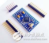
Arduino
I used the same Arduino board on the "Retro Watch", Arduino Pro Mini 3.3 volts (ATmega328). The reason for choosing it is that it can operate at 3.7 volts for lithium polymer batteries and its size. If you don't mind the size of the module and battery, but just use it for testing, then the Arduino Nano board is also a good idea (easy to implement and test). The Arduino Pro Mini operates at 8 MHz, and at 5 volts it is 16 MHz, but 8 MHz is sufficient. In general, you only need to prepare the Arduino Pro Mini 3.3 volt board and USB Asynchronous Receiver Adapter module.
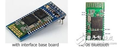
Bluetooth
Most of the Bluetooth modules you can get started with the HC-06 module and have a control interface board. There are reset buttons and working status LEDs on the interface board. It supports 3.3V or 5V working voltage, which is convenient, but the size is larger. LEDs are not required and consume power. So I used the HC-06 module directly and ignored the interface board.
Accelerometer
The MPU-6050 Acceleration/Gyro Sensor Module is used. If you have other similar accelerometers, you can use them instead. However, the source code will have to be changed.
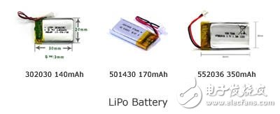
battery
Here I used a lithium polymer battery. The single-core lithium battery output voltage is 3.7 volts, allowing the Arduino Pro mini to work properly. Of course, there are also batteries of different sizes and capacities on the market. The battery size below 100 mAh is small, but continuous power supply is not guaranteed, and if the power is too low, the startup system is a problem. I recommend using a battery with over charge and discharge protection, which is better if it is made of a detachable socket.
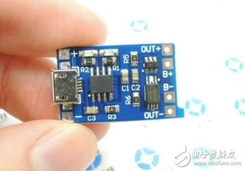
For convenience, you can also add a lithium battery charging module with a USB charging port to output power from the pin to the Arduino.
other materials
You need wires, soldering irons, switches, and battery holders. This assembly tutorial is also helpful to you.
Android section
The Android program of the retro bracelet runs in the Android 4.0 environment. If your Android version is lower than 4.0, or if you are using an iPhone, hehe...
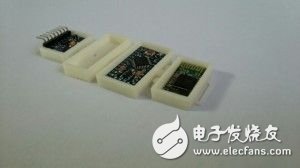
The third step: assembly
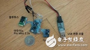
The figure shows the results of assembling each module except the battery. Now FTDI powers the entire module, so no battery is needed.
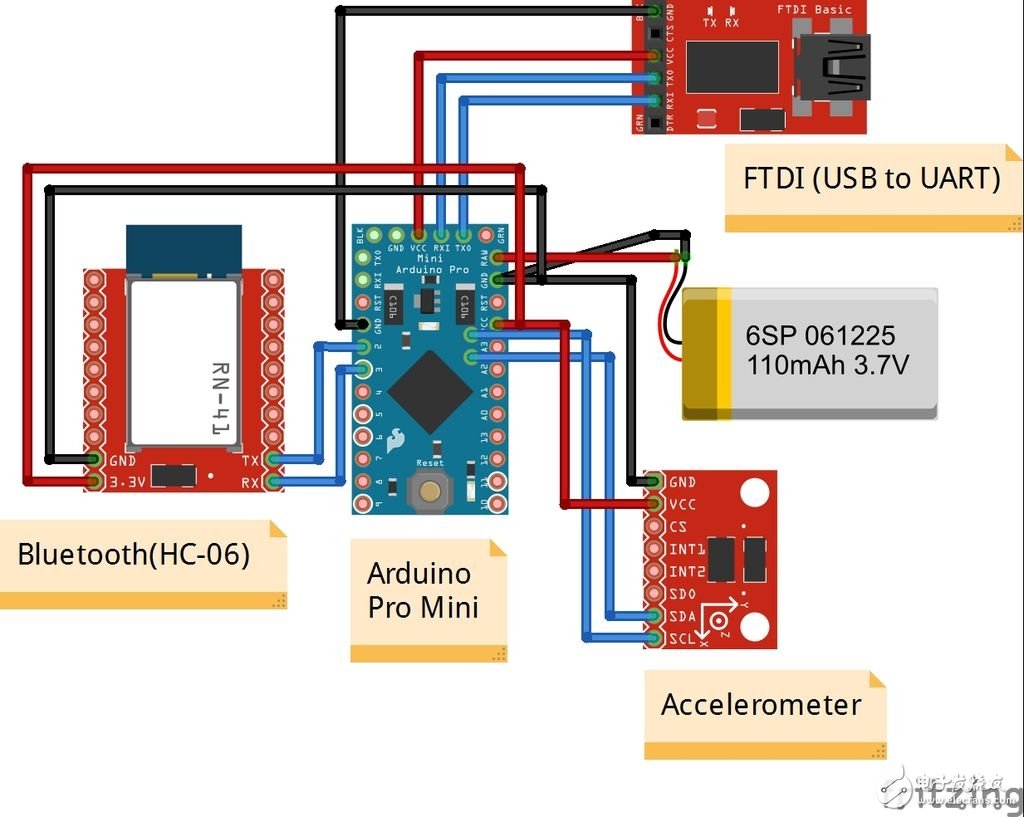
Connect Arduino-Bluetooth module
If you want to know how to pair test Bluetooth module, Baidu! Just follow the tutorial to wire the VCC, GND, TXD, RXD pins. (VCC is connected to 3.3 volts, GND is grounded, TX is connected to D2, and RX is connected to D3)
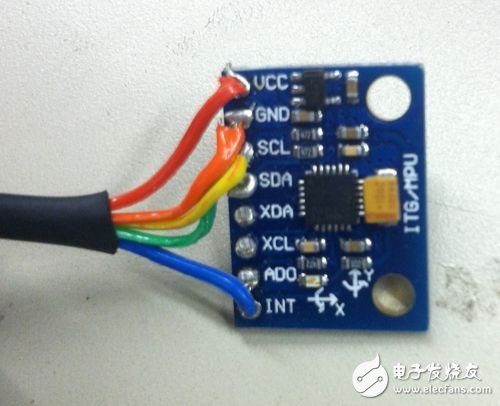
Connect Arduino-Accelerometer (MPU-6050)
The accelerometer module uses the I2C interface. (VCC is connected to 3.3 volts, GND is grounded, SDA is connected to A4, and SCL is connected to A5)
Connect Arduino-battery
Power supply is very simple, just connect the positive terminal to the input (RAW) and the negative terminal to ground (GND). If you want to have a charging function, then use the lithium battery charging module. This is, you should connect the B+ and B- of the battery to the positive and negative outputs of the charging module, and connect the positive and negative terminals of the output to the RAW and GND of the Arduino board.
Check connection
Once all the processes have been completed, it is the next step. In addition to the battery, each part is connected, the power is supplied by the FTDI module, and the battery is not connected before the source code is uploaded and the test is completed. When all tests have been completed, disconnect the FTDI module and connect the battery (or add the charging module).
Step 4: Arduino source code for the bracelet
On GitHub you can download the program framework of the bracelet
Upload Arduino source code
After the code is compiled, you need to upload it to the Arduino board. Before uploading, select the motherboard model "Arduino Pro mini 3.3 volts (ATmega328)" and press the reset button on the board before uploading. If the process fails, the following information feedback will be available:
Arvdud: stk500_getsync():not in sync: resp=0×00
The reason for displaying this information is usually:
1. The type of motherboard you choose in the Arduino development environment is different from the actual one. 2. The TX and RX pins are connected incorrectly. 3. The serial port pin used to connect the TX and RX pins has an error. 4. The boot boot failure on the board. 5. The user has used a USB module that does not support the auto reset function.
For the first case, you need to select the correct motherboard type in the [tools board] of the Arduino development environment; in the second case, check if the TX and RX pins are properly connected; if it is still in the third case after correction As mentioned, disconnect the D0 and D1 pins; in the fifth case, you simply press the reset button. When you press the upload button in the Arduino development environment, observe the information that appears, and at a time it will change from "Compiling" to "Uploading". If you see the TX/RXLED on the USB module flashing, the upload process is normal. The rare one is Case 4, then you use a UNO board to rewrite the failed boot module.
debugging
You need to make sure that each module is connected and working correctly. First run the serial monitor of the Arduino development environment to see if the accelerometer is working properly. (After the upload of the program code, the LED on the board will light up and run the program test.) Because the source code below has a segment error detection code, when the connection is normal, it should display the value sent back by the Arduino board. If not, it proves that there is a problem with the accelerometer connection. (After all debugging work is done, the error detection code can be removed.)
// Print the raw acceleration values ​​"br" Serial.print (F ( "accel x, y, z:")); Serial.print (accel_t_gyro.value.x_accel, DEC); Serial.print (F ( "," )); Serial.print(accel_t_gyro.value.y_accel, DEC); Serial.print(F(", â€)); Serial.print(accel_t_gyro.value.z_accel, DEC); Serial.print(F(", at ")); Serial.print(iAccelIndex); Serial.println(F(""));
Now it's time to check the Bluetooth module. After the VCC and GCN pins are connected accurately, the module scanned by the mobile device should be found. If the HC-06 module is not visible on the device list, check the power supply pins. After completing this step, it is time to check the application section.
Assuming the pairing process is normal, but the program application does not receive data, then there is a problem with the TX/RX pin connection. In other words, the data transfer from the Arduino to the Bluetooth module is abnormal.
Step 5: Install and run the application
Explain how to compile and modify the Android source code will be very long, so here is passed. However, you can download the entire retro bracelet Android source code on GitHub, modify it, and distribute it as long as you keep the copyright information. The source code for the Android app can be found in the [RetroBand_Android\RetroBand] folder.
I put the app on the Google App Store, just search for "RetroBand" and find it. It runs on Android 4.0 systems.
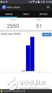
Install the application, run the program, and use the retro bracelet to correct the mobile device program to see if the application can successfully receive the information. The Android app has 3 list menus.
Timeline: Here you collect accumulated calorie data, you can find hourly, daily, and monthly calorie data.
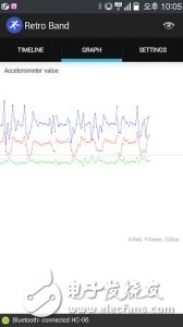
Chart: Display the data received by the accelerometer and plot it as a chart. You can see how the 3-axis data is transformed.
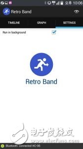
Settings: Configure the program settings here and enter your own weight. Other features will be open to the public.
If you successfully test the Android app, connect the lithium battery to complete the next work.
Retro bracelet technical parameters:
Processor: ATmega328-3.3v (8MHz), 32KB flash memory (2KB boot boot share), 2KB RAM, 1KB EEPROM.
Dedicated Android app for Android 4.0 or above.
The calorie calculation function based on the calculation of the number of steps.
Accumulate calorie data, and display the statistics in monthly, daily, and hourly manners.
Real-time monitoring of 3-axis data changes on the accelerometer.
Open source.
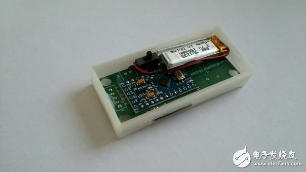
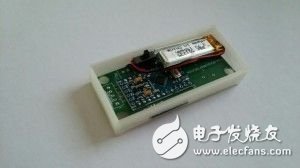
In the figure below you can see the prototype of the product - Arduino, accelerometer, Bluetooth module, charging module, lithium battery, power switch combination. I deliberately applied some glue to make it look dirty, but it still works.
Step 6: Packaging

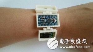
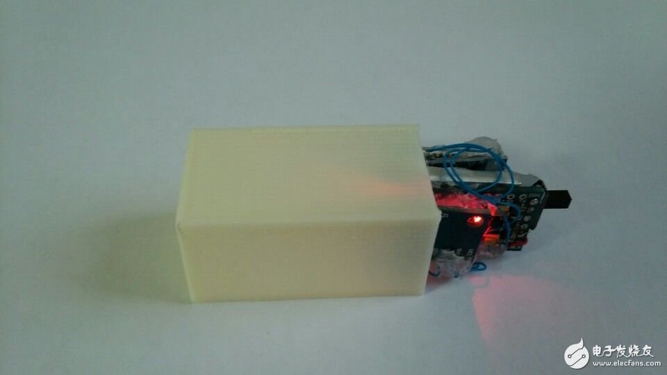
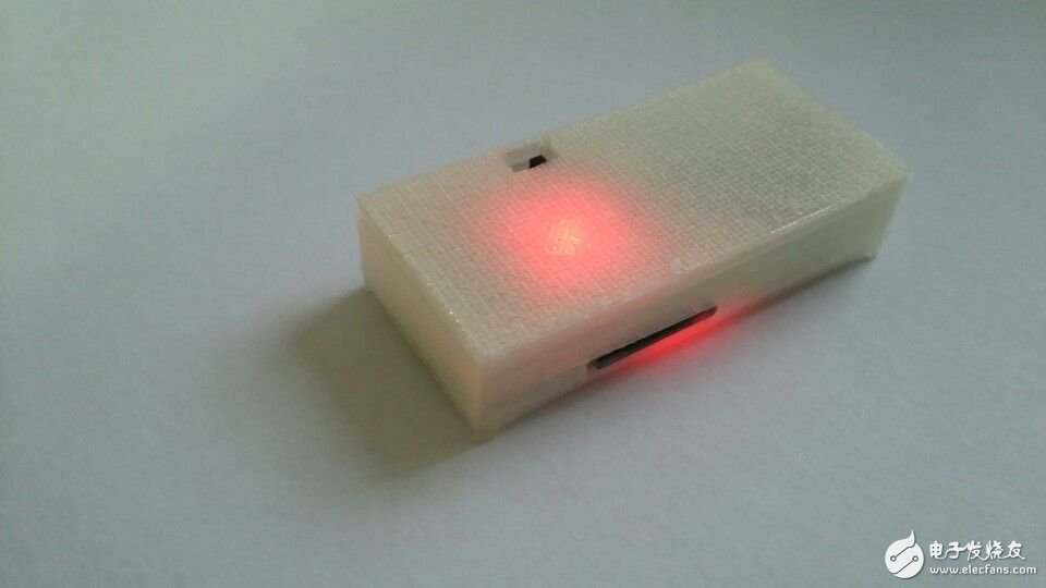
If you have a 3D printer, try your own design. The shell seen here is printed by a 3D printer.
Step 7: Postscript
The retro bracelet is my second work, the follow-up of the "made smart watch (retro watch)". My smart bracelet is too simple to use for other activity tracking products, but the Bluetooth module and accelerometer are the basic modules that are used in other works. According to my program source code, you can make different modifications.
I hope this tutorial will help you. Thanks to the following for helping me with this work.
Chang-Han Jeon, Il-Yong Park, Byung-Gyu Kim, KyungReol Ku, Sang-Won Lee, Kyung-Bu Jeong.
Reference Profile: HardCopyWorld.com
Original link original: GodsTale 
Bolt Down Fuse,Midi Fuse,Meqo Fuse,Anl Fuse
Dongguan Andu Electronic Co., Ltd. , https://www.idofuseholder.com