Summarize how high-speed digital circuits suppress noise

    In high-speed digital systems, the demand for advanced data processing and computing power has driven the miniaturization of chip process sizes and the increase in operating frequencies. Today’s processors operate at GHz levels, with digital signals exhibiting very short rise and fall times, which introduce higher harmonic components. As a result, these systems are characterized by high-frequency and high-bandwidth operation. For an assembled PCB, both the PCB itself and the package (Pkg) have resonant frequencies that fall within this range. If the power delivery system (PDS) is not designed properly, structural resonance can occur, leading to poor power quality and potential system failure. Moreover, as component density increases, low voltage and low swing designs are commonly used to reduce power consumption. However, low-voltage signals are more susceptible to noise interference. Common sources of noise include coupling, crosstalk, and electromagnetic radiation (EMI), but the most significant impact comes from simultaneous switching noise (SSN). The PDS system includes not only the circuit system but also an electromagnetic field formed by the power source and ground plane. The figure below illustrates a typical power transmission system. [Image: Schematic diagram of a typical power transmission system] When discussing ground bounce noise (GBN), it is common to focus only on the PCB and measure its S-parameter |S21| to assess GBN levels. Port 1 represents the location of the SSN excitation source—typically the active IC on the PCB. A smaller |S21| indicates a better PDS design and reduced GBN. However, noise originates from the IC, travels through the Pkg power system, and then via the substrate vias and solder balls to the PCB's power system. Therefore, it is essential to consider both the Pkg and PCB together to accurately model GBN behavior in high-speed digital systems. To study this, we designed a PDS structure (Figure 2) representing the Pkg power system mounted on the PCB. [Image: Schematic diagram of the BGA package mounted on the PCB] We measured the S-parameters of this structure using a network analyzer (HP8510C) and a probe station (Microtech) across a frequency range of 50 MHz to 5 GHz. Two 450 µm-pitch GS probes were used, connected to the power ring and ground ring of the Pkg signal layer. This setup is shown in Figure 3. [Image: Structural measurement of the BGA package mounted on the PCB] The results of the Pkg+PCB structure are shown in Figure 4. We also measured single Pkg and PCB structures for comparison to understand the differences between the full PDS system and individual components. [Image: Measurement results of the BGA package mounted on the PCB] From the measurements, it is clear that the GBN behavior varies significantly among the three structures. A single Pkg behaves like a capacitor below 1.3 GHz, with a resonant mode after 1.5 GHz. A single PCB shows a resonant mode after 0.5 GHz, such as at 0.73 GHz (TM01), 0.92 GHz (TM10), and 1.17 GHz (TM11), resulting in worse GBN performance than a single Pkg. When combined, the Pkg+PCB system exhibits additional resonance points before 1.5 GHz, caused by PCB coupling through solder balls and vias, which increases noise impact on the IC. Decoupling capacitors are traditionally used to suppress power plane noise. However, their placement, size, and number are often based on empirical rules. To study the ideal placement, we added decoupling capacitors to the Pkg, PCB, or both, and measured the effect on |S21|. [Image: Decoupling capacitors mounted on Pkg and PCB] We tested three scenarios: placing capacitors on the Pkg, on the PCB, or on both. With 100 nF capacitors, ESR of 0.04 Ω, and ESL of 0.63 nH, the results showed that adding capacitors on both Pkg and PCB provided the best noise suppression. However, adding capacitors only on the PCB introduced an extra resonance point near 800 MHz, worsening the situation. At higher frequencies (2–5 GHz), the capacitors became less effective due to their own resonant frequency limitations. The ESR of the decoupling capacitor affects the system response. Increasing ESR flattens the pole and fills the zero, leading to a flatter |S21| curve. Similarly, increasing ESL raises the resonance peak amplitude and shifts it to lower frequencies, reducing noise suppression effectiveness. The number of capacitors also plays a role. More capacitors generally lead to better noise suppression, especially in the low-frequency range. However, too many capacitors can introduce more resonance points, potentially amplifying noise if it aligns with those frequencies. Capacitor value selection depends on the frequency band being targeted. Large capacitors (e.g., 100 nF) are effective at low frequencies, while small capacitors (e.g., 100 pF) perform better at mid-frequencies. Mixing different capacitance values can broaden the noise suppression range but may also increase the risk of resonance issues. The thickness of the Pkg and PCB power planes also influences the S-parameters. Thicker Pkg layers shift the first zero point to lower frequencies, increasing PCB-coupled noise. In contrast, PCB thickness has a minimal impact at high frequencies but affects low-frequency performance slightly. Finally, the distance between the decoupling capacitor and the test point matters. Placing the capacitor closer to the noise source reduces inductance and improves noise suppression. If this is not possible due to packaging constraints, reducing the Pkg power layer thickness can help mitigate the issue. In conclusion, optimal decoupling requires careful consideration of capacitor placement, ESR, ESL, number, and value. The Pkg and PCB must be considered together, as each contributes to the overall noise behavior. Thin power planes and strategic capacitor placement are key to minimizing noise and ensuring stable power delivery in high-speed digital systems.

    19MM Metal Switches

    19MM Metal Switches

    19MM Metal Switches, also known as Metal Push Button Switch in harsh working environment. The most competitive advantage of this Metal Switches is that it is high mechanical life, in which momentary could reach 1,000,000 cycles and self lock is 500,000 cycles. Stainless steel is resistant to damage IK10, it is very hard and reliable. Therefore, this series of metal switch is widely used in automobiles, ships, medical and large mechanical equipment.

    In order to ensure the trust of our customers, this series Push On Push Off Switch has passed UL testing and certification, IP67 dust-proof and waterproof certification, TUV, European and American environmental protection RoHS and lead-free environmental protection certification .
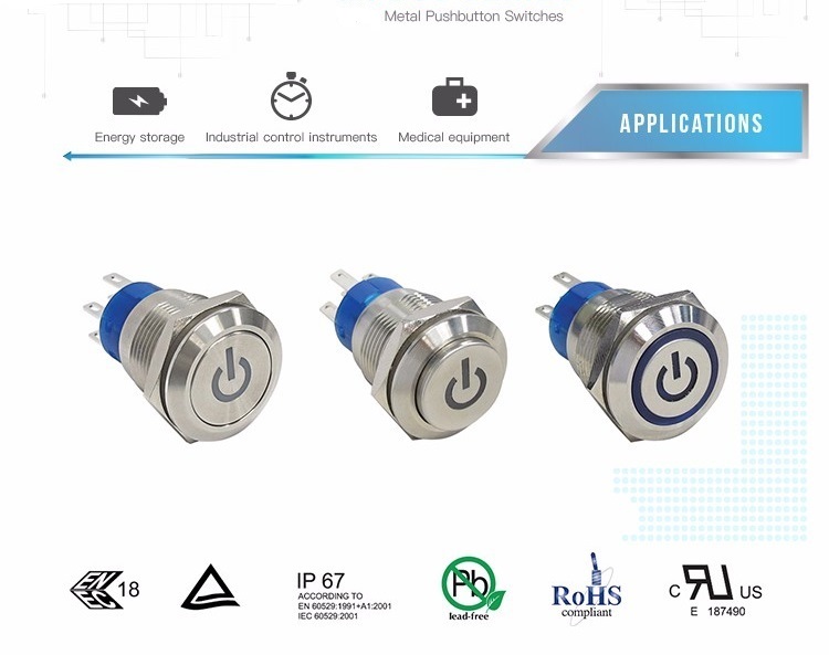


    Anti Vandal Switches


    Our 19mm Waterproof Push Button Switch have a variety of materials, including stainless, brass with nickel plated, brass with chrome plated, AI alloy with black anodized. This serious Push On Push Off Switch could offer different LED light, including white, red, yellow, green. Customer can select power logo indicator when controlling the power supply, customers could choose the double color indicator light when Switching different function.

    Furthermore, all the LED indicate light are provided by well-known LED lamp manufacturers, guarantying the long-term use of LED lights and high-life mechanical life
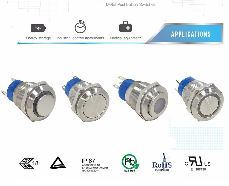

    Waterproof Push Button Switch

    19mm Metal Switch,Metal Push Button Light Switch,Waterproof Metal Push Button Switch,Waterproof Metal Push Button Switches,Metal Led Light Push Button Switch

    YESWITCH ELECTRONICS CO., LTD. , https://www.yeswitches.com

    Previous Post: Memory will not work! CPU cache is so important
    Next Post: Common sense needs to understand the specifications of flat-screen TV screens in the market
    Home
    Recent Posts
    • Littelfuse Introduces Metal Hybrid PPTC Miniatur…
    • Littelfuse Introduces Metal Hybrid PPTC Miniatur…
    • Memory will not work! CPU cache is so important
    • Summarize how high-speed digital circuits suppre…
    • Common sense needs to understand the specificati…
    • Common sense needs to understand the specificati…
    • The flexible battery printed on clothes or the f…
    • The flexible battery printed on clothes or the f…
    • Seven questions to get a simple understanding of…
    • Seven questions to get a simple understanding of…
    • Three-year Action Plan for the Development of a …
    • Three-year Action Plan for the Development of a …
    • Introduce the aspects of initial contact with AR…
    • Introduce the aspects of initial contact with AR…
    • Changfang Group expects full-year net profit to …
    • Changfang Group expects full-year net profit to …
    • Write a simple x86 kernel that can be booted wit…
    • Write a simple x86 kernel that can be booted wit…
    • How to debug labview? Case analysis of USB debug…
    • How to debug labview? Case analysis of USB debug…