
This article will disassemble the programming process by analyzing several cases, from the control process to the principle and the ladder diagram. If you use other series or brand PLC, its logical structure is very similar.
The classic example of a PLC schematic to a program - traffic signal control(1) Clear system control requirements
The system requires two buttons to control the traffic lights. The traffic lights are arranged as shown in the figure below.
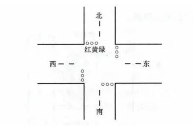
The system control requirements are as follows:
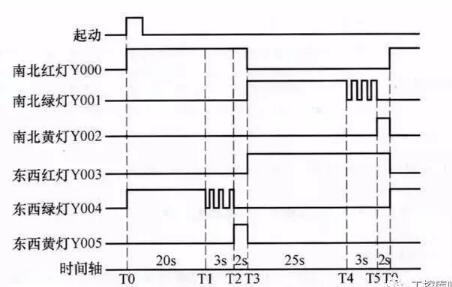
When the start button is pressed, the north and south red lights are on for 25s. In the time when the north and south red lights are on for 25s, the green light is first lit for 20s and then flashed 3 times with a frequency of 1/s. Then the yellow light is on for 2s, and after 25s, the north and south are red. The light goes out and the extinguishment time is maintained for 30s. During this 30s time, the red light is always on, the north and south green light is on for 25 seconds, then it flashes 3 times with a frequency of 1/s, and then the yellow light on the north and south lights up for 2s. Repeat this process later. After pressing the stop button, all lights are off. The working sequence of the traffic signal is shown in the figure below.
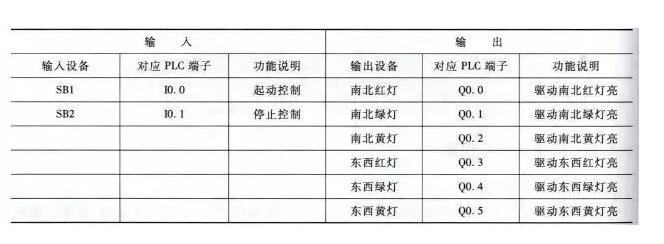
(2) Identify input/output devices and assign them suitable I/O terminals
The following table shows the input/output devices and corresponding PLC terminals required for traffic signal control.
(3) Drawing traffic light control circuit diagram
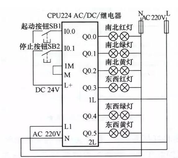
Control circuit diagram
(4) Write PLC control program
Start STEP 7-Micro/WIN programming software and write a ladder program that meets the control requirements. The completed ladder diagram is shown in the figure below.
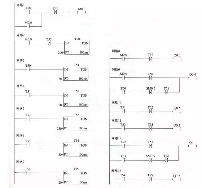
Ladder diagram
In the ladder diagram shown in the figure above, a special auxiliary relay SM0.5 is used, which is called the contact utilization type special relay. It uses the PLC to automatically drive the coil, and the user can only use its contacts to draw a ladder diagram. Can only draw its contacts. SM0.5 can generate a clock cycle of 1s, the high and low duration of each 0.5s, above the ladder network 9 as an example, when the T50 normally open contact is closed, within 1s, SM0.5 often closed touch The on-time and off-time of the point are 0.5 s respectively, and the Q0.4 coil power and time are all 0.5 s.
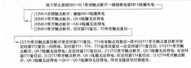
The following describes the working principle of the ladder diagram against the control circuit and timing diagram:
(1) Start control

(2) stop the control
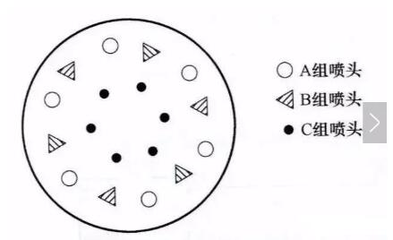
(1) Clear system control requirements
The system requires two buttons to control the A, B, and C groups of nozzles (by controlling the pump motors of the three groups of nozzles). The arrangement of the three nozzles is shown in the figure below.
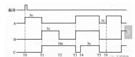
The system control requirements are as follows:
When the start button is pressed, group A nozzles stop after spraying for 5 seconds, then group B and group C spray at the same time. After 5 seconds, group B nozzles stop, group C nozzles continue to spray for 5 seconds and then stop, then group A and group B spray nozzles for 7 seconds. The nozzles of group C were stopped within the first 2 seconds of the 7 seconds, and the water was sprayed within 5 seconds. Then, the three groups of nozzles A, B, and C were simultaneously stopped for 3 seconds, and the foregoing process was repeated thereafter. After pressing the stop button, the three nozzles stop spraying at the same time. The following figure shows the timing chart of A, B and C nozzles.
(2) Identify input/output devices and assign them suitable I/O terminals
The input/output devices and corresponding PLC terminals required for fountain control are shown in the following table:
(3) Draw a fountain control circuit
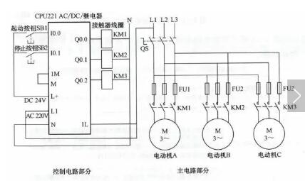
Control circuit diagram
(4) Write PLC control program
Start STEP 7-Micro/WIN programming software and write a ladder program that meets the control requirements. The completed ladder diagram is shown in the figure below.
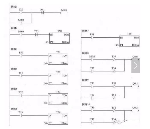
Ladder diagram
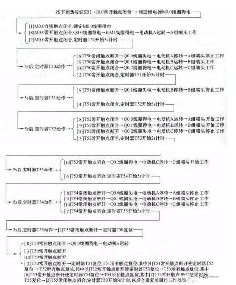
The following describes the working principle of the ladder diagram against the control circuit:
(1) Start control
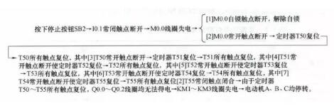
(2) stop the control
(1) Clear system control requirements
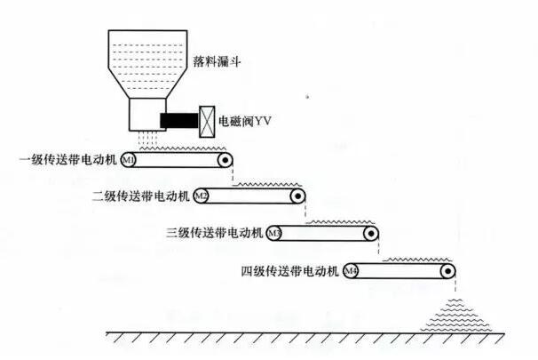
The system requires two buttons to control the conveyor belt to work in a certain way. The structure of the conveyor belt is shown in the figure below.
The system control requirements are as follows:
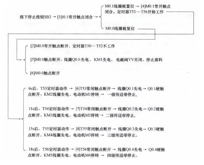
When the start button is pressed, the solenoid valve YV opens and starts blanking. At the same time, the primary conveyor motor M1 is started and the material is conveyed forward. After 6 seconds, the secondary conveyor motor M2 is started. After M2 is started for 5 seconds, the three-pole conveyor motor M3 is started. Four stages after the start of M3, the four-stage conveyor motor M4 is started.
When the stop button is pressed, in order to prevent material accumulation on the conveyor belts, it is required to close the solenoid valve YV first, and then stop M1 after 6 seconds. After M1 stops for 5s, let M2 stop, and M2 stops for 4s and let M3 stop. , M3 stopped after 3s to stop M4.
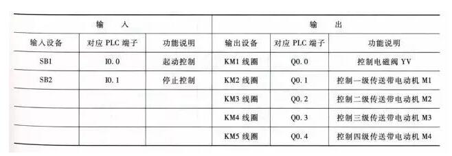
(2) Identify input/output devices and assign them suitable I/O terminals
The input/output devices and corresponding PLC terminals required for multi-level conveyor control are shown in the following table.
(3) Drawing multi-stage conveyor control circuit diagram
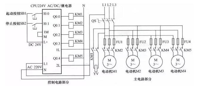
Control circuit diagram
(4) Write PLC control program
Start STEP 7-Micro/WIN programming software and write a ladder program that meets the control requirements. The completed ladder diagram is shown in the figure below.
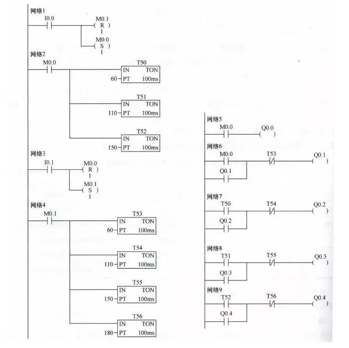
Ladder diagram
The following describes the working principle of the ladder diagram against the control circuit.
(1) Start control
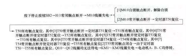
(2) stop the control
(1) Clear system control requirements
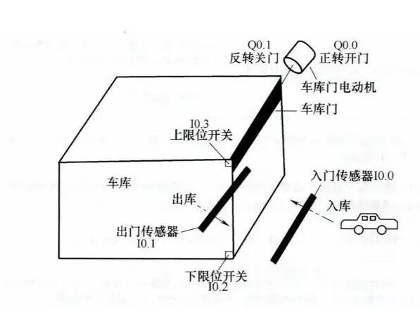
The system requires the garage door to open and close automatically when the vehicle enters or exits. The control structure of the garage door is shown in the figure below.
The system control specific requirements are as follows:
When the vehicle goes through the entry sensor, the entry sensor switch is closed, the garage door motor rotates, and the garage door rises. When the garage door rises to the upper limit switch, the motor stops; when the vehicle goes through the exit sensor, the exit sensor switch Closed, the garage door motor reverses, the garage door descends, and the motor stalls when the garage door is lowered to the limit switch.
When the vehicle exits through the exit sensor, the exit sensor switch is closed, the garage door motor rotates, and the garage door rises. When the door rises to the upper limit switch, the motor stops; when the vehicle exits through the entry sensor, the entry sensor switch is closed. The garage door motor is reversed and the garage door is lowered. When the door is lowered to the limit switch, the motor stops.
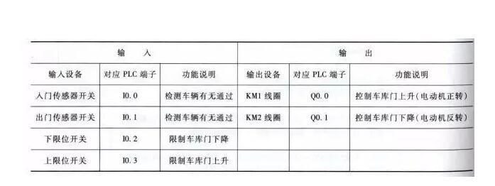
(2) Identify input/output devices and assign them suitable I/O terminals
The input/output devices and corresponding PLC terminals required for garage automatic door control are shown in the following table:
(3) Draw a garage automatic door control circuit
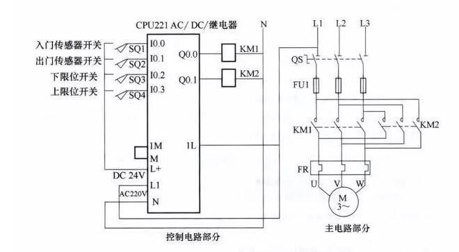
Control circuit diagram
(4) Write PLC control program
Start STEP 7-Micro/WIN programming software and write a ladder program that meets the control requirements. The completed ladder diagram is shown in the figure below.
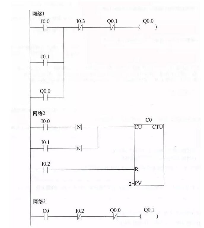
Ladder diagram
The following describes the working principle of the ladder diagram against the control circuit.
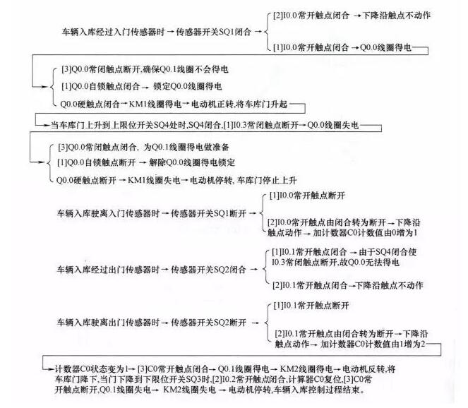
(1) Storage control process
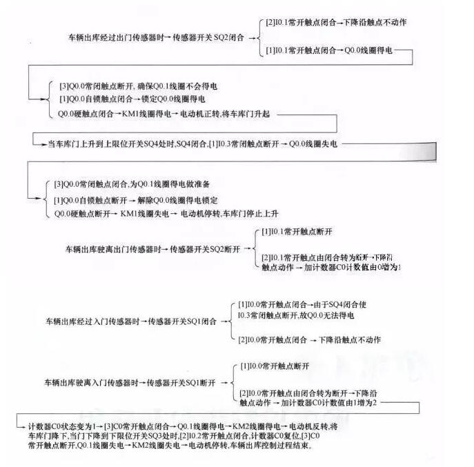
(2) Outbound control process
Thyristor module is one of the most commonly used semiconductor devices because of its small size, simple structure and strong function.This device has been widely applied in various kinds of electronic equipment and electronic products, used as a rectifier, inverter, frequency, voltage regulator, contactless control of motor speed, motor excitation, non-contact switch and the power control, etc.
Thyristor Module,High Current Thyristor Module,Air Cooling Thyristor Module,Standard Voltage Thyristor Module
YANGZHOU POSITIONING TECH CO., LTD. , https://www.cnpositioning.com