
This paper presents an intelligent temperature control system based on the S7-200 series PLC, highlighting its implementation and the use of serial communication between the host computer and the PLC within a VB environment. After on-site testing, the system demonstrates high reliability and ease of monitoring. Given the widespread use of PLCs in industrial applications, this system has broad potential for deployment across various industries.
PLCs are widely recognized for their strong control capabilities, high reliability, flexible configuration, simple programming, and ease of expansion. As a result, they have become essential tools in modern and future industrial automation systems. Temperature control is a critical aspect in many industrial processes. However, traditional temperature control methods often suffer from low precision and significant overshoot, leading to issues such as poor product quality and energy waste.
To address these challenges, an intelligent temperature control system based on PLC technology has been developed. This system offers wide application potential. While PLCs excel in control functions, they lack strong data processing and user interface capabilities. This limitation can be effectively addressed by integrating a computer into the system. A master-slave real-time monitoring system combining a computer and a PLC leverages their respective strengths, enabling decentralized control and centralized monitoring. The system uses Siemens S7-200 PLC connected via serial communication with a computer, providing a stable and user-friendly interface.
1. PLC Temperature Control System
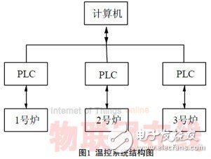
In boiler temperature control systems, electric heating boilers are commonly used in process control. Temperature control is a key component in these systems. The structure of the PLC-based temperature control system is illustrated in Figure 1. The PLC controls the furnace's heating and cooling through heating elements and fans. Meanwhile, the computer allows users to set target temperatures, display real-time data, and adjust parameters, thereby enabling effective temperature monitoring.
2. System Composition
The system includes signal processing and temperature adjustment functions. In temperature control, common temperature sensors like thermocouples or resistance temperature detectors (RTDs) are used to collect temperature signals. These signals must be converted into standard voltage or current signals before being processed by an analog-to-digital converter. Therefore, a transmitter is typically used to condition the sensor output. The S7-200 series PLC commonly uses the EM235 module, which supports four analog inputs and one analog output. After processing the temperature signal, the PLC outputs a current signal that controls the power supply’s conduction ratio, thus adjusting the heater’s power output to achieve precise temperature control. The system diagram is shown in Figure 2.

3. Implementation of PID Temperature Control
The PID (Proportional + Integral + Derivative) algorithm is used for controlling analog signals. The S7-200 series PLC includes a dedicated PID loop instruction, making it easy to implement PID control. The algorithm involves calculating the error between the setpoint and the process variable, and then applying proportional, integral, and derivative terms. Before executing the PID instruction, a parameter table must be initialized. The actual values must be scaled appropriately before the PID operation to ensure accurate control. The output is then converted back to the engineering unit for driving the actuator.
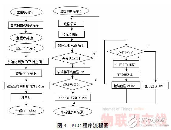
In practice, the system uses a three-stage control approach: initially, full power is applied to overcome thermal inertia; then, PID control is activated once the temperature reaches a certain level; finally, the power is gradually reduced to maintain the desired temperature. This method helps reduce overshoot and improve stability. The program flowchart is shown in Figure 3.
Adjusting PID parameters is crucial for optimal performance. There are two main approaches: theoretical calculation and engineering tuning. While theoretical methods rely on mathematical models, engineering tuning is more practical and widely used. Common techniques include the critical gain method, reaction curve method, and decay method. In this case, the critical gain method was employed, involving steps such as selecting a sampling period, adding proportional control until critical oscillation occurs, and calculating PID parameters accordingly.
4. Design of PLC and Computer Communication
VB is chosen for its powerful graphical interface and ease of use, making it ideal for implementing communication between the upper computer and the lower PLC. The lower-level device is the S7-200 PLC, while the upper computer communicates with it via an RS-232 serial port.
4.1 PLC Program Part
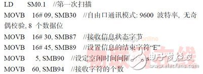
The S7-200 supports multiple communication modes, including free port communication. In this mode, the PLC can use commands such as XMT and RCV, along with interrupt handling, to exchange data with the host computer. The communication settings are configured using registers like SMB30, and the program initializes the communication protocol and baud rate. The initialization procedure is shown in Figure 4.
4.2 Upper Computer Program Part
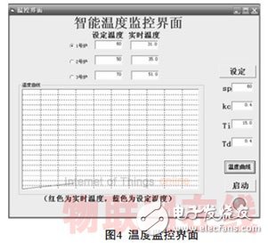
VB provides the MSComm control, which simplifies serial communication between the PLC and the computer. The program includes features such as temperature display, dynamic graph plotting, parameter setting, and data exchange with the PLC. The communication setup involves configuring the COM port, baud rate, and data length. Once the port is open, the program can read temperature data from the field and send control commands to the PLC. The interface is shown in Figure 5.
5. Conclusion
This paper introduces a temperature controller based on the S7-200 series PLC and discusses the serial communication technology between the PLC and the computer in a VB environment. It also provides some sample programs. The example demonstrates that the system is reliable and easy to monitor, making it suitable for a wide range of industrial applications.
Anti-rat ant Solar Cable is a kind of cable specially used for photovoltaic power generation system, its main function is to prevent small animals such as mice and ants from destroying the photovoltaic line.
The characteristics of anti-rat ant solar cable are as follows:
1. Anti-ant performance: anti-rat ant solar cable adopts special materials and technology treatment, has strong anti-ant performance, and can effectively prevent the invasion of ants and other small animals.
2. Anti-bite performance: anti-rat ant solar cable has good anti-bite performance, can resist the bite of mice and other animals, to avoid short circuit, fire and other safety hazards.
3. Weather resistance: anti-rat ant solar cable is made of high-quality materials, has good weather resistance, and can run stably for a long time under various harsh environmental conditions.
4. Easy installation: The installation method of anti-rat ant solar cable is the same as that of ordinary light cable, without additional tools and equipment, easy and quick installation.
5. Efficient performance: anti-rat ant solar cable has low resistance and high conductivity, which can ensure the efficient operation of photovoltaic system.
In short, the anti-rat ant solar cable is a kind of cable specially designed for photovoltaic power generation system, with the characteristics of ant-proof, anti-bite, weather resistance, easy installation and efficient performance, which can effectively protect the solar cable from the damage of small animals such as mice and ants.
Anti-Mouse Ants Solar Cable,Adapter Cable,Ant Rat Resistant Solar Cable,Ant Resistant Dc Cable
Suzhou Yonghao Cable Co.,Ltd. , https://www.yonghaocable.com