
 The following is the circuit diagram of [LM431 designed delay switch circuit]
 Delay switch circuit designed by LM431
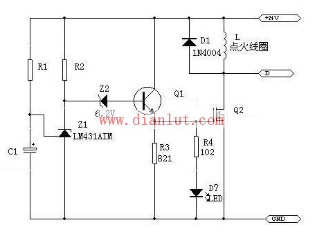
Working principle: R1 and C1 form a delay circuit, the delay time is required to be 1 second, and C1 should use a tantalum capacitor that can work at -55 ~ 125 °C. After power-on, the LM431 input terminal is low level, the output terminal is about 23 volts, Q1 and Q2 are turned on, the ignition coil is energized for a short time, and the current is about 24 amps. After one second of power-on, the LM431 input terminal rises to 2.5 volts due to At this time, the output of the LM431 is about 2. volt, so the Zener Z2 with a regulation value of 6.2V should be connected in series at its output, so that Q1 and Q2 can be turned off and the ignition coil is de-energized. The ignition coil is an inductive load, the DC resistance is about 1 ohm, and the working power supply is a 24 volt battery. The measured current is about 25 amps. The operating temperature range of this circuit can reach -40 ~ 121 °C, which can fully meet the requirements of automotive electronics.
(Editor: Circuit Diagram)KNBL1-32 Residual Current Circuit Breaker With Over Load Protection
KNBL1-32 TWO FUNCTION : MCB AND RCCB FUNCTIONS
leakage breaker is suitable for the leakage protection of the line of AC 50/60Hz, rated voltage single phase 240V, rated current up to 63A. When there is human electricity shock or if the leakage current of the line exceeds the prescribed value, it will automatically cut off the power within 0.1s to protect human safety and prevent the accident due to the current leakage.
leakage breaker can protect against overload and short-circuit. It can be used to protect the line from being overloaded and short-circuited as wellas infrequent changeover of the line in normal situation. It complies with standard of IEC/EN61009-1 and GB16917.1.
KNBL1-32 Residual Current Circuit Breaker,Residual Current Circuit Breaker with Over Load Protection 1p,Residual Current Circuit Breaker with Over Load Protection 2p
Wenzhou Korlen Electric Appliances Co., Ltd. , https://www.korlen-electric.com