
1 Introduction
PWM (PulseWidthmodulaTIon) type switching regulator power supply has the advantages of small size and high efficiency, and has been widely used as a power supply device in many fields. However, the short-term interference of the switching transistor's operating state transition period and wide spectrum is its Achilles heel. It not only affects the switching power supply itself, but also interferes with other nearby electronic devices.
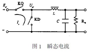
When the switching regulator power supply is working, the switching transistor and the freewheeling diode (which can also be another switching transistor) are always turned on or off alternately. In Figure 1, KQ and KD are not ideal devices, and the conversion of the two states takes a certain time. This creates spikes. During the state transition, the turned-on switch is not fully turned on, and the turned-off switch has no turn-off instant, and the power supply has a direct path to the ground, generating a transient current Is. The current is related to the difference between the current Imax when the switching transistor is turned on and the current Icmin when it is turned off, and the duration at which the switches KQ and KD are simultaneously turned on. Ringing oscillations occur on the waveform due to the influence of the circuit distribution parameters.
2 The effect of the duration of the instantaneous turn-on of the power switch on spike interference
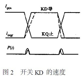
The turn-on and turn-off times of a transistor are inversely proportional to its cutoff frequency. The shorter the turn-on and turn-off time, the faster the switching speed. The duration of simultaneous conduction depends on the switching speed of the device used by KQ and KD. Compared with switching devices with different speeds, the faster the switching device is, the shorter the duration of conduction, and the narrower the peak interference and the larger the amplitude.
3 Reduce the voltage spike caused by the leakage inductance of the transformer
The greater the leakage inductance of the transformer, the higher the voltage spike and the greater the RF interference. Especially after the transformer is shielded, the leakage inductance is correspondingly larger due to the poor coupling. In general, a transformer wound with a toroidal core produces a leakage inductance that is smaller than that of an E-type. In addition, the winding process is also very important. The better winding method is to bypass the primary half of the total number of turns, then the total number of turns around the secondary, and finally the remaining half of the primary, that is, the secondary coil in the primary coil. intermediate. Thus, the primary coil maintains a good coupling, giving the transformer a small leakage inductance.
4 Influence and suppression of switching waveform of power tube on spike interference
The squareness of the switching waveform Usr(t) affects spike interference. The harmonic amplitude of a rectangular wave decreases with frequency by 20dB octave, and the trapezoidal wave is 40dB? Ten times the frequency. Deliberately changing the steepness of the rectangular wave and the degree of passivation of the two corners can suppress high frequency components and reduce spike interference. Therefore, it is necessary to reasonably select the switching speed of the switching transistor and the freewheeling diode.
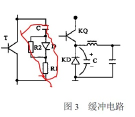
For switching triodes, there are two ways to reduce spike interference, which is to increase the rise time of Vce and reduce the fall time of Ic. In the circuit of FIG. 2, after determining KQ, it can be seen from FIG. 3 that increasing the turn-on time of KD and decreasing the turn-off time can reduce spike interference.
Voltage range of the AC power supply is: 100~240V
The wide range makes the charger compatiable with the voltage standard in all countries
Certificate/Conformity to standards:IEC/IECEX/CE/ROSH/IP68/ISO/EX
The combination of layers and modules is convenient and is unnecessary to use a crane for movement.
User safety, electro Enameled covered with paint and electrical protection according to their performance.
Simplely designed charging borad easy for maintanance
Evse Charging Station,Evse Electric Vehicle,Electric Vehicle Service Equipment,Electric Vehicle Charging Test Equipment
ZHEJIANG HUACAI OPTIC-TECHNOLOGY CO LTD , https://www.win3safety.com