
Recently, the Digilent open-source community has been asked a couple of times about how to implement an SPI interface on Zynq SoC and Zynq UltraScale+ MPSoC. After answering these questions, I felt it would be beneficial to write a detailed article explaining the process and share it with others.
When working with Zynq SoC or Zynq UltraScale+ MPSoC in your design, there are two main approaches to implementing an SPI interface:
1. Utilizing the built-in SPI controller on the Processing System (PS) side, which includes two available SPI controllers.
2. Using the AXI Quad SPI (QSPI) IP core configured for standard SPI communication on the Programmable Logic (PL) side.
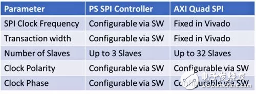
Depending on your application requirements, you can choose between these methods. Both implementations support all four SPI modes and can function as either a master or a slave. The table below highlights some key differences between the two options:
To begin with, we'll demonstrate how to use the PS-side SPI controller for SPI communication. This involves selecting the SPI module in the Zynq MIO configuration tab and connecting it to the SPI interface of the Digilent Arty Z7 board using EMIO.
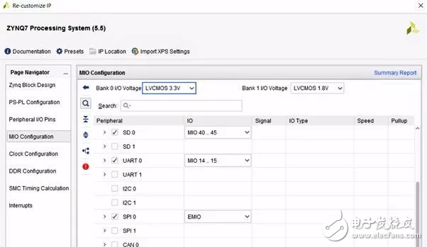
Figure: Enabling SPI and mapping ports to EMIO
Once the configuration is set, the next step is to connect the I/O signals to the SPI port. The correct wiring is essential—any mistake could lead to unexpected results during testing. For example, when used as a slave, an additional Slave Select signal is required, while a master uses three select lines.
After setting up the I/O correctly and generating the project, you can configure the SPI controller as a master or slave through the application settings. To interact with the PS SPI controller, you need to use the API functions provided by the Xilinx BSP, such as those defined in xspi_ps.h. In our first example, we configured the SPI as a master.
By default, SPI transfers 8 bits at a time. However, you can also configure it for 16 or 32-bit transfers. When using 16 or 32 bits, you must ensure that the data types match the API functions, which typically require u8 buffers. This can sometimes cause compiler warnings if not handled properly.
Here are the two primary API functions for transferring data:
S32 XSpiPs_Transfer(XSpiPs *InstancePtr, u8 *SendBufPtr, u8 *RecvBufPtr, u32 ByteCount);
S32 XSpiPs_PolledTransfer(XSpiPs *InstancePtr, u8 *SendBufPtr, u8 *RecvBufPtr, u32 ByteCount);
To handle 16- or 32-bit data, you can cast your buffer to a u8 pointer like this:
XSpiPs_PolledTransfer(&SpiInstance, (u8*)&TxBuffer, (u8*)&RxBuffer, 8);
This setup allows for 8, 16, or 32-bit transfers. As a demonstration, I connected the SPI master to the Digilent Digital Discovery pocket instrument to verify the transmitted data. We adjusted the data width from 8 to 16 bits in the software to test the functionality.
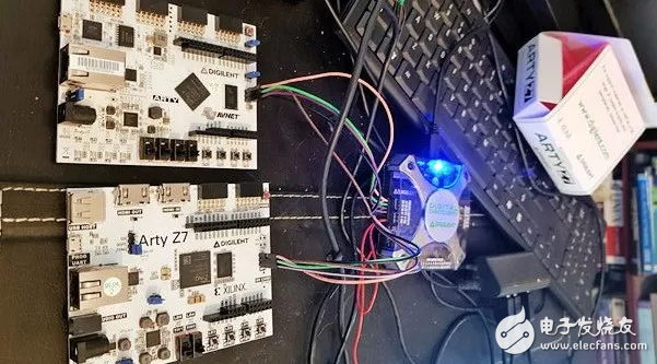
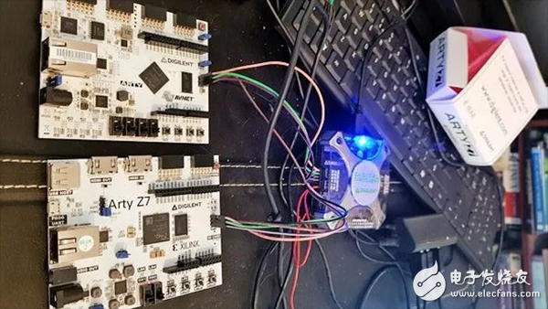
Figure: Arty Z7 development board with Digital Discovery pocket instrument
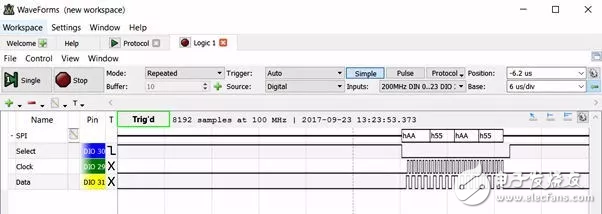
Figure: Zynq SoC PS SPI master sends four 8-bit words
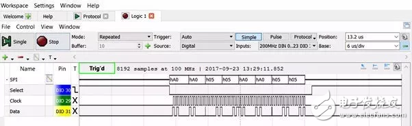
Figure: PS SPI master sends four 16-bit words
Another approach to implementing SPI is by using the AXI QSPI IP core. This method requires more configuration in Vivado and may take longer to set up. In the AXI QSPI configuration dialog, you can adjust parameters like width, frequency, and number of slaves. One of the most important settings is whether the core acts as a master or a slave. If you're configuring it as a master, make sure to enable the master mode option. If it's a slave, disable that option so the SPISel input pin is available. This pin needs to be connected to the master’s slave select port when acting as a slave.
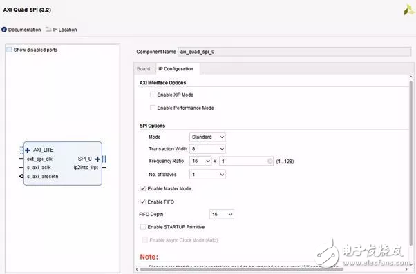
Figure: Configuring the AXI Quad SPI
Photovoltaic Single-Axis Tracking Bracket
Photovoltaic Single-Axis Tracking Bracket,One Axis Solar Tracker Solar,Solar Tracker Solar Racking Tracker,Solar Racking Tracker System Single-Axis
Hebei Shuobiao New Energy Technology Co., Ltd. , https://www.pvbracketsystem.com