
This paper presents a simple yet practical intelligent power monitoring system for Uninterruptible Power Supply (UPS) applications, designed to operate effectively in various complex power grid environments. The system is highly intelligent, featuring self-diagnostic capabilities, automatic display, alarm functions, status memory, and communication functions. It ensures reliable and efficient power management in critical applications.
The system modules communicate via internal RS485 buses, enabling real-time monitoring, control, and alarm handling of AC power distribution, battery charging and discharging processes, battery status, voltage regulation, bus-to-ground resistance, and feeder switch conditions. Additionally, it communicates with the host computer through an RS232 interface for historical data retrieval and analysis.
The main monitoring unit serves as the central controller of the entire system. It includes a main monitoring board, a 320x240 dot matrix LCD display, a keyboard, and indicator lights. This unit manages battery charge and discharge operations, sets and displays operational parameters, stores and retrieves alarm records, and communicates with the host computer via RS232. It also controls internal units through the RS485 bus.
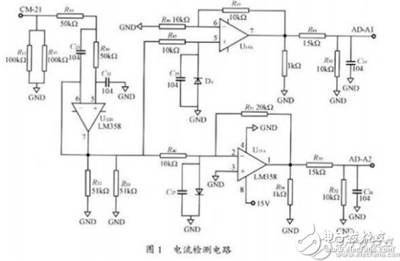
The accuracy of battery charge and discharge current detection is crucial. The circuit diagram is illustrated in Figure 1. Since the circuit detects both charging and discharging currents, the voltage across the small resistor changes direction. Therefore, the circuit uses two separate channels for detection, making signal conditioning easier and allowing measurement using a single A/D input channel.
**Battery Detection and Inspection Unit**
This unit comprises a battery detection board and an optional battery inspection board. It collects battery voltage (mother voltage), charge/discharge current, ambient temperature, and cell voltage. It also checks the fuse status and outputs analog voltage and current references to control other manufacturers’ modules or phase-controlled power supply three-phase trigger boards, enhancing system compatibility. The unit performs time-based measurements, triggers alarms for over-voltage, over-charging, battery feed, and single-cell failure, and allows adjustment of battery voltage and cell voltage display values by adjusting potentiometers on the test and patrol boards, as shown in Figure 2.
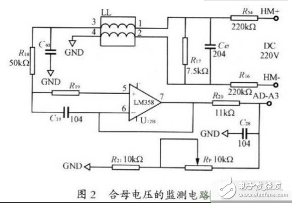
The mother voltage monitoring circuit is depicted in Figure 2. The combined voltage passes through resistors R16, R17, and R54, with sampling occurring at R17. Thus, R17 must be a high-precision resistor. R16 and R54, being much larger, do not require high precision due to their position in the denominator. The LL component suppresses common-mode interference, and the potentiometer Rp adjusts the monitored voltage to match the A/D converter’s input requirements.
**A/D Conversion**
The system employs the TLV1544 A/D conversion chip. Key features include a wide single-supply operating range (2.7–5.5 V), fast conversion time (less than 10 μs), four external input channels, programmable selection of input channels, and a synchronous serial interface connected via SPI to the microprocessor. An 11-bit resolution is sufficient for the system, as shown in Figure 3.
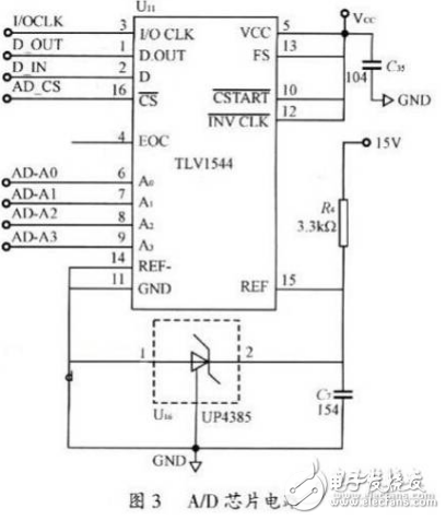
The A/D conversion process begins with sampling the selected analog input. The sampling starts from high to low, and the sample-and-hold function activates from low to high, initiating the analog-to-digital conversion. The conversion is independent of clock signals and starts when the signal is high. The switched capacitor array's sampling duration is controlled during the low period. When unused, it remains high. The EOC pin goes high upon completion of the A/D conversion, signaling that the process is done. The system checks the EOC level to determine if the conversion is complete.
**Summary:**
This paper outlines the design of an intelligent power monitoring system, focusing on battery charge and discharge management tailored to battery characteristics. This approach enhances battery longevity and reliability in real-world applications.
Tantalum Alloys,Tantalum Turned Parts,Tantalum Alloy Target,Tantalum Alloy Wire
Shaanxi Xinlong Metal Electro-mechanical Co., Ltd. , https://www.cnxlalloys.com