1. Direct Addressing
The S7 series PLC programming instructions support both direct and indirect addressing methods. Direct addressing involves specifying the exact memory address of a signal, which can be used for various elements like I, Q, M, SM, V, L, S, T, C, AC, HC, etc.
For example, in Figure 8-4.1, the program uses direct addressing to output the contents of flag memory MB10 to QB2. The MOV B instruction is a byte move command in S7-200 PLC. EN is the enable input, IN is the source address, and OUT is the destination address. The SMO.O represents an internal constant "1" signal. More details on this instruction can be found in the relevant sections of the PLC programming manual.
2. Indirect Addressing
In indirect addressing, the operand specifies the address where the data is stored, rather than the data itself. This method requires the use of an "address pointer," which is a register that holds the address for indirect access.
Key points to consider when using indirect addressing in S7-200:
- Only variables V, local variables L, or accumulators AC1, AC2, AC3 can act as address pointers (AC0 is not supported).
- To set up an address pointer, the required memory address must be moved into the pointer in double-word format. The address is marked with the "&" symbol, indicating it refers only to the address, not the actual data.
- When accessing data through an address pointer, a "*" should precede the operand to indicate that it is an indirect address.
- The address pointer can access I, Q, V, M, S, timers T, counters C, but cannot access AI/AQ, HC, SM, or local variables L. Indirect addressing is not suitable for binary bit signals, high-speed counters, or local variables.

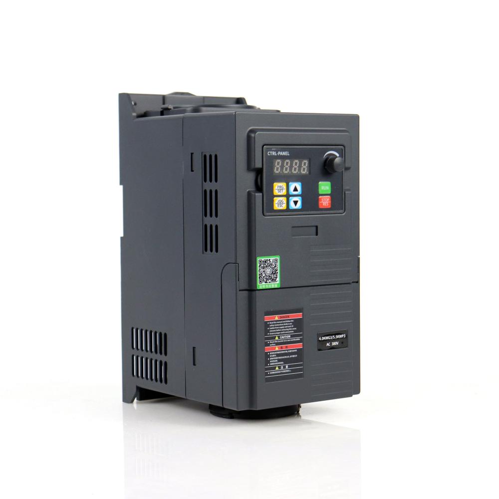
A single-phase VFD, also known as a variable frequency drive, is a specialized electronic device used for precise control and regulation of single-phase motors. Unlike three-phase motors that are commonly used in industrial applications, single-phase motors are predominantly found in residential and small-scale applications.
The primary function of a single-phase VFD is to control the frequency and voltage supplied to the single-phase motor, thereby enabling accurate regulation of motor speed. By adjusting the frequency and voltage output, the VFD allows for smooth and precise control over the motor's rotational speed. This feature is particularly useful in applications where speed control is required, such as in residential HVAC systems, small-scale machinery, and household appliances.
Energy efficiency is a significant advantage offered by single-phase VFDs. By adjusting the motor speed to match the load requirements, the VFD reduces energy wastage and improves overall energy efficiency. When the motor operates at a lower speed during periods of low demand, energy consumption is significantly reduced, resulting in energy savings and lower operating costs.
Motor protection is another important aspect addressed by single-phase VFDs. They incorporate various protective features, including overload protection, short circuit detection, and thermal protection, which help safeguard the motor against damage due to excessive current, voltage fluctuations, or overheating. This ensures reliable motor operation, prolongs the motor's lifespan, and reduces the risk of unexpected failures.
Harmonic filtering is also a critical consideration in single-phase VFD applications. When single-phase VFDs operate, they can introduce harmonics into the power supply, which may cause issues such as voltage distortions and interference with other electrical equipment. To mitigate these problems, single-phase VFDs often incorporate harmonic filtering techniques to suppress harmonics and ensure a clean and stable power supply, maintaining power quality and preventing damage to connected equipment.
Control algorithms play a significant role in single-phase VFD operation. These algorithms allow for precise control and adjustment of motor speed, ensuring smooth acceleration, deceleration, and accurate speed regulation. Advanced control algorithms enable efficient motor operation and enhance overall system performance.
In summary, single-phase VFDs provide precise control and regulation of single-phase motors in residential and small-scale applications. With their energy efficiency, motor protection features, harmonic filtering capabilities, and advanced control algorithms, single-phase VFDs enhance motor performance, reduce energy consumption, and ensure reliable operation in various residential and small-scale applications.

Three Phase Vfd,Ac Single Phase Gasoline Generator,220V Vfd,Ac Inverter
WuXi Spread Electrical Co.,LTD , https://www.vfdspread.com
