
The RX3i power modules are designed for simplicity and flexibility, functioning like standard I/O modules that plug directly into the backplane. These modules are compatible with any standard RX3i CPU, making them ideal for a wide range of applications. One of their key features is automatic voltage adaptation, which eliminates the need for jumpers when selecting different input voltages. This makes installation and configuration more user-friendly.
Additionally, each power module includes a current limiting function that automatically shuts down in case of a short circuit, preventing potential damage to hardware. The tight integration between the power module and the CPU ensures reliable stand-alone control, as well as fail-safe and fault-tolerant operation. Other notable features include advanced diagnostics and built-in smart switch fuses, enhancing both performance and safety.
The RX3i power module supports multiple input voltage options, including 100~240VAC, 125VDC, 24VDC, or 12VDC, offering versatility for various environments. The specific models and their performance parameters are detailed in Table 1-3. Most power modules require two slots on the backplane, except for the IC695PSD040, which only needs one slot. The Universal Power Module (IC695) is designed to work with a universal backplane, while the expansion power module (IC694) must be installed in the leftmost power socket on the expansion backplane, excluding the rightmost slot.
Below are images showing the appearance of the IC695PSD040 and IC695PSA040 power modules.
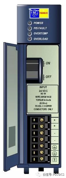
*Appearance of IC695PSD040*
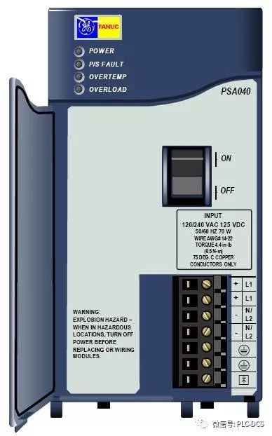
*Appearance of IC695PSA040*
Taking the IC695PSD040 as an example, this module operates with an input voltage range of 18~39VDC and provides a stable 24VDC output with 40W of power. The module features four LEDs that indicate its operational status:
1. **POWER** – Green means the power module is supplying power to the backplane; amber indicates that power is applied but the switch is off.
2. **P/S FAULT** – Red LED shows a fault, meaning the module isn't providing sufficient voltage.
3. **OVERTEMP** – Amber LED indicates the module is overheating.
4. **OVERLOAD** – Amber LED signals that the output power is near or exceeding its limit.
If the **P/S FAULT** LED turns red, the module has failed and cannot supply enough voltage. If the **OVERTEMP** or **OVERLOAD** LEDs are lit, it means the module is either overheating or overloaded. In such cases, the PLC fault table will display the corresponding error information.
The ON/OFF switch is located behind the front panel and controls the output of the power module, but it does not cut off the input power. A protruding part near the switch helps prevent accidental activation.
The +24V, -24V, ground, and MOV terminals can be connected using a single wire ranging from 14 to 22 AWG.
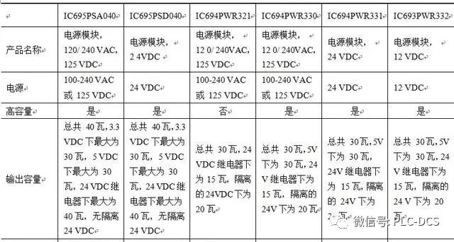
*Model and performance parameters of the power module of the RX3i*
Esd Tvs Diode,Esd Protection Diode,Esd Suppressor Diode,Usb Esd Protection Diode
Shenzhen Kaixuanye Technology Co., Ltd. , https://www.icoilne.com