Design and Implementation of DVI Receiver Based on FPGA

    The DVI (Digital Video Interface) was introduced in 1999 by the Digital Display Working Group to use the minimum transformed differential signal (TMDS) as the basic electrical link for transmitting digital video signals. The image source generates red, green, and blue color signals along with control signals, which are encoded and serialized by the DVI transmitter using a clock signal. These signals are then sent through the TMDS channel to the DVI receiver, where they undergo serial-to-parallel conversion, alignment, decoding, and other processing before being displayed. This process is illustrated in Figure 1. DVI transmits digital signals directly, eliminating the need for analog-to-digital conversion, saving time, and improving efficiency. Additionally, it is fully compatible with HDMI in terms of electrical characteristics, making system upgrades more straightforward. The DVI link structure is shown in Figure 1. When receiving DVI signals over long distances, traditional methods involve using a dedicated receiving chip and an FPGA. However, this approach can increase power consumption and cost. To address this, a method has been proposed that leverages the built-in TMDS I/O interface of an FPGA, eliminating the need for external components. This allows users to implement the design quickly, reducing the overall development cycle. DVI supports a single TMDS link with 24-bit color depth. If higher color depth is required and the system confirms that both the graphics card and display support dual-link TMDS, the system initiates a dual-link configuration. In this case, link 0 (data channels 1–3) transmits 24-bit data, while link 1 (channels 4–6) handles additional color information. When resolution and refresh rate exceed the capacity of a single TMDS link (which has a maximum pixel frequency of 165 MHz), the system uses two links: link 0 transmits odd pixels, and link 1 transmits even pixels. Since both links share the same clock, the clock frequency in dual-link mode is halved compared to single-link operation. The DVI encoder uses TMDS encoding to convert 8-bit pixel data into 10-bit symbols and 2-bit control signals into 10-bit symbols as well. The least significant bit is transmitted first, ensuring minimal transformation and DC balancing—two key advantages of the TMDS protocol. **1 Receiver Design** **1.1 System Architecture** The DVI receiver system includes level conversion, clock recovery, phase adjustment, serial-to-parallel conversion, word alignment, channel alignment, and decoding. The serial signal from the TMDS channel is ultimately converted into three 8-bit pixel channels and two 2-bit control signals, as shown in Figure 2. **1.2 Clock Recovery and Phase Adjustment** Clock recovery and synchronization are critical in DVI receiver design. The pixel clock from the DVI signal serves as the reference. The serial data on the TMDS channel is 10 times the reference clock frequency. This rate is sampled using DDR (Double Data Rate) technology, allowing sampling at twice the serial data rate. Thus, the reference clock only needs to be multiplied by 5 times, reducing resource usage. After long-distance transmission, the data and clock may experience significant phase shifts, affecting correct sampling. Phase adjustment is necessary. The IODELAY module within the FPGA's IO interface is used to dynamically adjust the delay of the serial data, optimizing the sampling window. Compared to the DCM module, IODELAY lacks some outputs but can simulate their behavior. The phase adjustment algorithm ensures the sampling clock aligns with the center of the valid window, maximizing reliability. **1.3 Serial/Parallel Conversion** Serial-to-parallel conversion is performed using ISERDES in the FPGA’s IO interface module. This method avoids timing issues and saves resources compared to using multiple registers. For 1:10 conversion, two ISERDES modules are used, one as the master and the other as the slave. Their outputs are connected to each other, as shown in Figure 4. **1.4 Word Alignment** Word alignment is achieved using BITSLIP functionality or selector logic. The core idea is to detect control words after conversion and select the correct byte order using multiplexers. This ensures accurate data alignment before further processing. **1.5 Channel Alignment** Each channel receives a signal indicating whether the word alignment is valid. Once all three channels are aligned, the FIFO buffer starts writing and reading data. If a control word is detected, the corresponding channel is delayed until the others also detect the control word, ensuring synchronized output. **1.6 DVI Decoding** After channel alignment, the 8-bit pixel data and 2-bit control signals are decoded according to the DVI standard. When DE=0 (blanking period), the 2-bit control signal is decoded; when DE=1, the 8-bit pixel data is processed. **2 Simulation Results** The design was simulated using ModelSim 6.5, with the H264E_VDATA file used to generate R, G, B signals. The input to the receiver includes TMDS differential signals and a clock. The output consists of R, G, B signals, a recovered clock, and control signals like hsync, vsync, and de. The design was implemented on a Xilinx Virtex-5-330T FPGA. Resource utilization is listed in Table 1. Due to the PLL’s maximum frequency limit of 450 MHz, the main clock operates at 90 MHz, allowing a theoretical TMDS input rate of 900 Mb/s. In testing, a DVI signal from a PC graphics card was successfully received and decoded. The output was connected to a video processing module, producing a clear and noise-free dynamic image at 1280×720 resolution with a 74.5 MHz pixel clock, confirming the feasibility of the design. This paper presents a DVI receiver design compliant with the DVI 1.0 specification, demonstrating that using an FPGA for DVI decoding reduces resource usage, improves integration, and makes full use of available FPGA capabilities. **References** [1] Wang Chunjun, Pan Wei. The DVI Interface Should Be Embedded in Embedded System[J]. Computer Engineering, 2005, 31(20): 207-208. [2] Yin Shuxian, Xu Huosheng. Analysis and Logic Implementation of DVI Core Technology[J]. LCD & Display, 2007, 22(6): 765-769. [3] Feng Yongmao, Wang Ruiguang, Ding Titou. Digital Video Interface-DVI1.0[J]. Electronic Technology Application, 2003, 29(9): 10-14. [4] Xilinx. Virtex-5 FPGA user guide[EB/OL]. (2009-03-19)[2013-06-01] [5] FENG B, CRABILL E. Video connectivity using TMDS I/O in Spartan-3A FPGAs [EB/OL]. (2008-07-25) [2013-06-01] [6] Xilinx. Virtex-5 libraries guide for HDL designs [EB/OL]. (2009-09-16) [2013-06-01]

    Solar Engergy System

    Solar energy system, off gird pv system, grid pv system, solar power system, Solar Panel system, on grid solar system, grid tied solar system,20kw solar system


    Solar energy system include Solar photovoltaic system: 1. Off grid photovoltaic system mainly consists of solar modules, controllers, and batteries. To supply power to AC loads, it is also necessary to configure an AC inverter. 2. Grid connected photovoltaic power generation system. 3. Distributed photovoltaic power generation system. Distributed power generation or distributed energy supply.


    solar cell type mono crystalline, half cut cell
    solar energy pv system include on grid system, off grid system, hybrid system
    solar configuration solar panel, inverter, battery, bracket cabels, mc4 connector


    Product details and pic
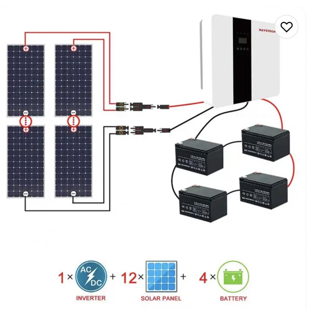
    Complete Off Grid Solar SystemOff Gird System 1 Jpg


    Solar Engergy System,Gird Solar Power System,Pv System For Carport,Energy System Off Grid Solar System

    PLIER(Suzhou) Photovoltaic Technology Co., Ltd. , https://www.pliersolar.com

    Previous Post: Design and Implementation of DVI Receiver Based on FPGA
    Next Post: Wafer manufacturing is pouring into the automotive electronics market and the line of first-line auto parts is blurring
    Home
    Recent Posts
    • What are these ghosts? Inventory of unpractical …
    • What are these ghosts? Inventory of unpractical …
    • How to calculate the length of the Huffman tree …
    • How to calculate the length of the Huffman tree …
    • Where is the new version of the itunes12 applica…
    • Where is the new version of the itunes12 applica…
    • Connect me box P8 to install sofa butler through…
    • Connect me box P8 to install sofa butler through…
    • Shanxi Luan Environmental Protection Energy Deve…
    • Artificial intelligence rises to national strate…
    • The Internet of Things is not just a smart brace…
    • The Internet of Things is not just a smart brace…
    • Overview of ISO/IEC RF ID Application Technology…
    • Overview of ISO/IEC RF ID Application Technology…
    • Overview of PTN-based mobile backhaul solutions
    • How Home Theater Cabling Home Theater Cabling Ti…
    • Is Huaxing Optoelectronics listed? How much is H…
    • Basic idea and principle of lms algorithm
    • Detailed explanation of jtag working principle
    • Detailed explanation of jtag working principle