
Long-term use of a three-phase asynchronous motor often leads to the loss or ambiguity of labels on the lead wires of the stator’s three-phase windings, resulting in confusion about the start and end terminals. This confusion can cause serious accidents, such as motor damage, due to incorrect connections. Therefore, accurately identifying the start and end terminals of the stator’s three-phase winding is crucial for safe and proper operation.
There are several common methods for determining the start and end terminals of the stator windings:
1. Residual Magnetism Method
1) First, identify the three windings.
Use a DC milliampere meter (or the mA/uA range of a multimeter) to test the six lead wires of the three-phase winding. Group them into three pairs based on continuity, which will help identify the individual windings.
2) Determine the start and end terminals using the residual magnetism method.
Connect the milliampere meter across two groups of windings. The remaining four leads can be connected in series, as shown in Figure 1a. Slowly rotate the motor rotor by hand. If the milliampere meter shows no movement or minimal swing, the connection is correct (i.e., the start and end are properly matched), as seen in Figure 1a. If the pointer moves significantly, swap the ends of one group not connected to the meter and try again, as in Figure 1b. If there is still movement, it indicates that the two windings connected to the meter have either both starts or both ends. Adjust the connections until the meter shows no movement, confirming the correct start and end positions.
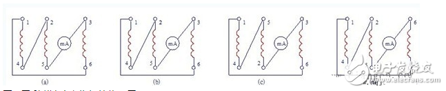
Figure 1: Determining the start and end of the winding using the residual magnetism method
In this method, the residual magnetism in the rotor induces an electromotive force in the stator windings when rotated, allowing the milliampere meter to distinguish between the start and end terminals. However, the magnitude of this induced voltage depends on the rotor's remanence, the number of coil turns, and the speed of rotation. It is important to pay attention to the following during measurement:
- The rotor must have residual magnetism, meaning the motor should have been operated before.
- The rotor must be rotated at a uniform speed to ensure consistent results.
An alternative way to detect residual magnetism is by rotating the rotor. If the meter shows no movement or no current indication (as in Figure a), the winding connections are correct—meaning the three start terminals (1, 2, 3) are connected together, and the three end terminals (4, 5, 6) are also correctly connected. If there is a current indication (as in Figure b), it means there is a connection error. Adjust the connections and repeat the test until no current is detected.
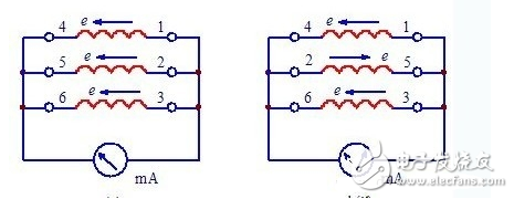
Figure 2: Using residual magnetism and ammeter method
The principle is that when the connections are correct, the vector sum of the three-phase currents is zero, so the ammeter shows no reading. If the start and end are incorrectly connected, the current will not cancel out, and the ammeter will show a reading.
2. AC Induction Method
Use a 36V low-voltage transformer to test the stator windings. Rub the leads of the three-phase windings, and the pair that sparks are grouped into three sets.
Next, connect the ends of the three groups (e.g., 4, 5, 6) together and connect them to one side of the transformer’s output. Take one wire from each group (e.g., 3) and connect it to the other side of the transformer’s output. Then, rub the remaining two wires (e.g., 1 and 2). If no spark occurs, it indicates that 1 and 2 are the start or end terminals. Swap one of the wires (e.g., 2) and repeat the process with 1 and 3. If no spark appears, then 1, 2, and 3 are all either start or end. If sparks occur, swap one of the wires (e.g., 4, 5, or 6) and continue testing until no spark is produced, thereby identifying the same-name terminals.
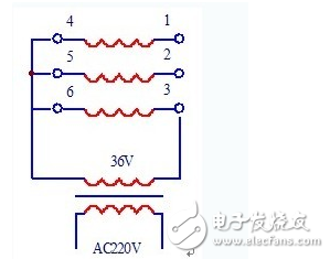
Figure 3: AC induction method (external power supply)
This method can also be performed using an AC voltmeter. Connect wires 3 and 6 to the transformer’s output and measure the voltages U32 and U31 between the 3–2 and 3–1 terminals. If U32 ≈ U31 > U36, then 1, 2, and 3 (or 4, 5, 6) are the start or end terminals. If U32 ≈ U31 < U36, it means that 3 and 6 are reversed. Swap them and test again. If U32 < U36 and U31 < U36, it suggests that 1 and 4 are reversed, and swapping them should resolve the issue.
The underlying principle of this method is based on the fact that when the same-name terminals are connected in series, the induced voltages cancel each other out. When different-name terminals are connected, the voltages add up. By applying AC voltage to one winding and measuring the induced voltage in the others, you can determine whether the start and end terminals are correctly identified.
Braided Sleeve,Braided Cable Sleeve,Expandable Braided Sleeving,Braided Wire Sleeve
Shenzhen Huiyunhai Tech.Co., Ltd. , https://www.cablesleevefactory.com