If you own a motorcycle, a motorhome, a fleet vehicle, a lawn mower, a daily commuter, or an old classic car, you’ve probably faced the issue of a lead-acid battery that won’t hold a charge. Over time, if the battery is left uncharged or improperly charged, it can develop sulfate crystals on its plates. These crystals prevent the battery from fully recharging and significantly reduce its capacity. When you try to recharge it, you might only get heat and water loss, without any real improvement in the battery’s voltage. This is a sure sign that the battery is on its way to being completely dead.
However, if the battery has a resting voltage of at least 1.8 volts per cell and no internal shorts, there's hope. A desulfation circuit can help break down those sulfate crystals and restore some life to the battery. This circuit is designed to be added to or modified from a standard battery charger, and it helps address the sulfate problem effectively.
Note:
Before starting this project, always remember: the power supply can be dangerous. If you're not confident in your skills, don't attempt this—safety first! It's better to ask for help than to risk injury or damage.
Project Overview:
To begin, find an old charger—whether large or small, depending on the size of the battery you’re working with. The bigger the charger, the better, as it will offer more flexibility. Start by removing everything except the transformer and rectifier. Some older models use finned rectifiers that cause high voltage drops, so replace them with a more robust bridge rectifier capable of handling higher current. All secondary wiring should be thick and short to minimize resistance. Mount the rectifier securely to the chassis to keep it cool and efficient.
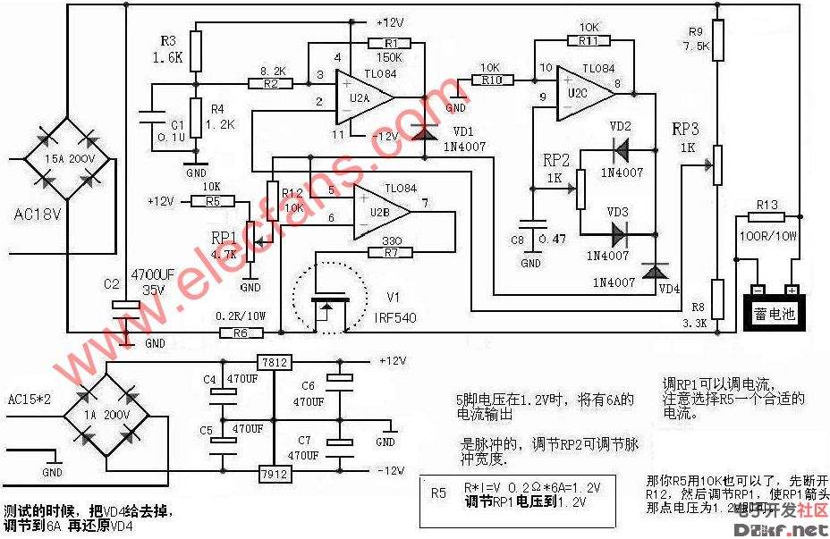
If your charger has a high/low switch, that’s a bonus. If not, you can adjust the secondary winding in some cases. The core of the circuit is a 14-stage ripple counter and oscillator IC 4060, which generates the pulse signal. This pulse is then fed into a 555 timer, which controls the duration of the output. A switch lets you choose between a long or short pulse. The 555 timer drives a transistor, which triggers a zero-crossing optically isolated TRIAC (model 3041), allowing the charger’s transformer to operate smoothly with a soft start and snubber circuit.
A small power supply is needed for the control circuit. Use a 15V 0.1A secondary transformer, a bridge rectifier, a voltage regulator, and two capacitors. Since this is a charging circuit, performance may vary slightly depending on components used. But don’t worry—it doesn’t mean the circuit isn’t working. Efficiency can still be good.
The snubber capacitor should be an X-type AC capacitor, and the power supply should have at least a 0.5W resistor. You can use a bidirectional thyristor like the BTA 25.600, but in most cases, a smaller one would work just fine. No PCB required!
How It Works:
In short, the goal is to apply enough voltage to dissolve the sulfates without boiling or damaging the battery. This is done by using short, high-voltage pulses followed by rest periods. A short pulse lasts about 0.5 seconds on and 3 seconds off, while a long pulse is around 1.4 seconds on and 2 seconds off. These times can vary slightly depending on component tolerances.
If you notice the electrolyte boiling during the process, switch back to the short pulse mode. Never leave the process unattended—monitor it closely until you understand how your specific setup behaves. I built this version about 10 years ago, and it worked well. However, there's always room for improvement, and others might enhance it further with modern components or design tweaks.
DongGuan BoFan Technology Co.,Ltd. , https://www.ufriendcc.com
