
UC3854AN
The UC3854AN is a Teacher's Rate Corrector (PFC) integrated circuit with 16 pins. Its functions are as follows:
1) GND - Ground connection.
2) PKLMT - Peak limit terminal, connected to the negative voltage terminal of the current sensing resistor. It shuts off the circuit when the current peak exceeds a certain threshold.
3) CAOUT - Current amplifier CA output.
4) ISENSE - Current sensing terminal, internally connected to the negative terminal of the CA input. Externally, it is connected to the positive terminal of the current sensing resistor via a resistor.
5) MULT OUT - Multiplier output, another end of the current detection. Internally, it outputs from the multiplier/divider and connects to the positive end of the CA input. Externally, it is connected to the negative terminal of the current sensing resistor via a resistor.
6) JAC Input - Current input terminal, internally connected to the multiplier/divider input. Externally, it is connected to the positive end of the rectified input voltage.
7) UA OUT - Voltage amplifier UA output, internally connected to the multiplier/divider input. Externally, it is connected to an RC feedback network.
8) URMS - RMS power supply voltage terminal, internally connected to the square-squared multiplier/divider input. It has a feedforward function, and the URMS value range is between 1.5V and 4.77V.
9) REF - Reference voltage terminal, generates a 7.5V reference voltage.
10) ENA - Start terminal, controls circuit voltage, oscillator, soft start, etc., through a logic circuit.
11) USENSE - Output voltage detection terminal, connected to the input negative terminal of the voltage amplifier UA.
12) RSET - External resistor RSET terminal, controls the oscillator charging current and limits the maximum output of the multiplier/divider.
13) SS - Soft starter.
14) CT - External capacitor CT terminal, where CT is the oscillator timing capacitor, allowing the oscillation frequency to be calculated as f = 1.25 / (RSET × CT).
15) Vcc - Integrated circuit supply voltage Vcc, with a rated value of 22V.
16) GTDRV - Gate drive terminal, connected to the gate of the power MOS switch tube through a resistor. The terminal potential clamp is at 15V.
Download PDF for UC3854 Control Power Factor Corrector Circuit Design
Download UC3854 PDF Data Sheet
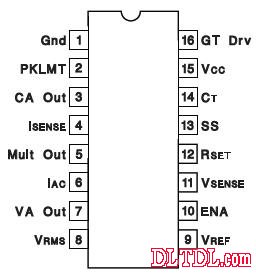
Figure 1: 16-pin Package
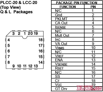
Figure 2: 20-pin Diagram Package
Figure 3: Internal Circuit Diagram
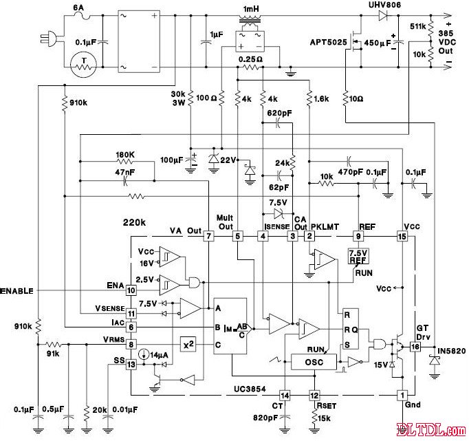
Figure 4: Typical Design Circuit Diagram
This integrated circuit is widely used in power factor correction applications due to its robust features and reliability. The UC3854AN ensures efficient energy conversion and minimizes power losses, making it ideal for various power supply designs.
For more detailed information or specific application requirements, please refer to the official datasheet provided by the manufacturer. Additionally, engineers often find the UC3854AN useful in designing circuits that require precise control over power factors, especially in high-power applications like industrial equipment and renewable energy systems.
Feel free to download the PDFs mentioned above for further reference. If you have any questions or need assistance with implementing this IC in your project, don't hesitate to reach out to technical support teams or forums dedicated to electronics design.
Features
A push button switch is a switch that has a knob that you push to open or close the contacts. In some pushbutton switches, you push the switch once to open the contacts and then push again to close the contacts. In other words, each time you push the switch, the contacts alternate between opened and closed. These types are commonly called latching switches. There are also Non latching push button switches that only maintain the switch contacts when the switch is help in position. Once the switch is let go, the current is broken and the switch turns off. Push switches are usually a simple on-off switch.
Push On Off Switch,Small Push Button Switch,Automotive Push Switch,Miniature Push Button Switch
Ningbo Jialin Electronics Co.,Ltd , https://www.donghai-switch.com