
The UC3854AN is a teacher's rate corrector (PFC) integrated circuit with 16 pins. Its primary functions include:
1) GND: Ground terminal
2) PKLMT: Peak limit terminal, connected to the negative voltage terminal of the current sensing resistor. It shuts off the circuit when the current peak exceeds a threshold.
3) CAOUT: Current amplifier CA output
4) ISENSE: Current sensing terminal, internally connected to the negative terminal of the CA input. Externally, it connects to the positive terminal of the current sensing resistor through a resistor.
5) MULT OUT: Multiplier output, which serves as the other end of the current detection. Internally, it outputs to the CA input positive end, while the external end connects to the voltage negative terminal of the current sensing resistor via a resistor.
6) JAC: Input current terminal, internally connected to the multiplier/divider input. Externally, it connects to the positive end of the rectified input voltage.
7) UA Out: Voltage amplifier UA output, internally connected to the multiplier/divider input. Externally, it connects to an RC feedback network.
8) URMS: RMS power supply voltage terminal, internally connected to the square-squared multiplier/divider input. It includes a feedforward function, with an URMS value range of 1.5~4.77V.
9) REF: Reference voltage terminal, generating a 7.5V reference voltage.
10) ENA: Start terminal, controlling circuit voltage, oscillator, and soft start through a logic circuit.
11) USENSE: Output voltage detection terminal, connected to the input negative terminal of the voltage amplifier UA.
12) RSET: External resistor RSET terminal, controlling the oscillator charging current and limiting the multiplier/divider maximum output.
13) SS: Soft starter
14) CT: External capacitor CT terminal, serving as the oscillator timing capacitor, setting the oscillation frequency to f=1.25/RSET*CT.
15) Vcc: Integrated circuit supply voltage Vcc, with a rated value of 22V.
16) GTDRV: Gate drive terminal, connected to the gate of the power MOS switch tube through a resistor, with a terminal potential clamp at 15V.
Download the PDF for UC3854 Control Power Factor Corrector Circuit Design Download the UC3854 PDF Data Sheet
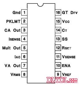
Figure 1: 16-pin Package Diagram
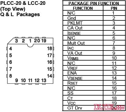
Figure 2: 20-pin Package Diagram
Figure 3: Internal Circuit Diagram
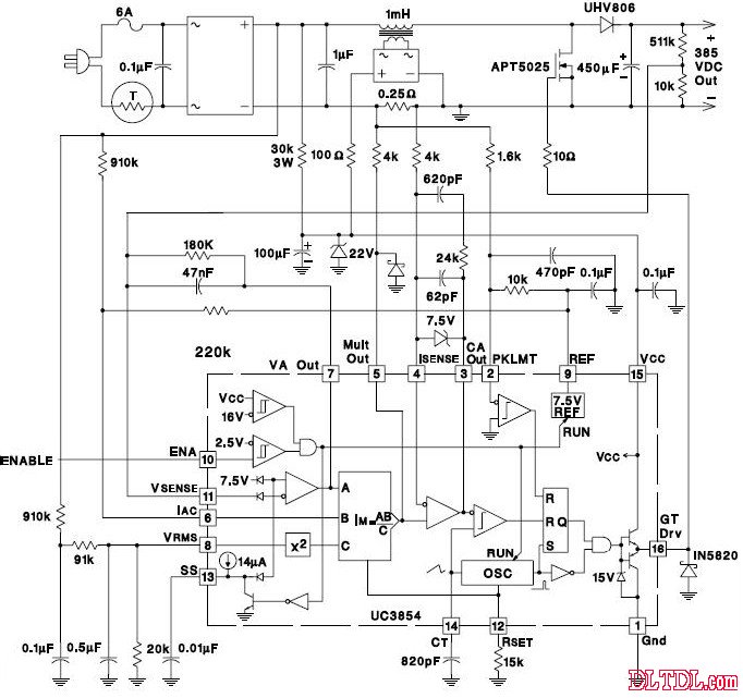
Figure 4: Typical Design Circuit Diagram
Specifications:
Mechanical life: More than 50.000 cycles
Electrical life: More than 100,000 cycles
Environment temperature Range: - 25 degrees ~ 85 degrees
Operating Relative Humidity Range: ≦96% RH, +40°C
Features
WIDE APPLICATION
Widely used for various kinds of electrical products, instrument, car, boat, household appliances such as lights, water dispenser, treadmill, coffee pot, speaker, electric car, motorcycle, TV, massage machine etc.
EASY TO INSTALL AND USE
2 PIN on-off Rocker Switch with SPST design, simple installation, freely turn on or off the load which you want to control.
HIGH OPERATING LIFE
Made of high quality polyamide eP(Nylon PA66) material, this sturdy mini boat rocker switch is born for anti-corrosion,anti-acid and high resistant with silver terminals.100,000 times of ON/OFF operating life span.
Small Rocker Switch,Micro Rocker Switch,Single Pole Rocker Switch,Single Rocker Switch
Ningbo Jialin Electronics Co.,Ltd , https://www.donghai-switch.com